am3zzn00008441
|
PTC HEATER
id071100002700
Purpose
Function
Structure/Construction
am3zzn00008441
|
Operation
1. When the ignition is switched ON (engine on), the dash-electrical supply unit receives (1) signals from each part.
|
Part |
Signal |
Condition |
|---|---|---|
|
Climate control unit
|
Airflow temperature setting signal
|
Target temperature not controlled
|
|
PCM
|
Ambient temperature signal
|
Less than 20 °C {68 °F}
|
|
PCM
|
Engine coolant temperature signal
|
Less than 70 °C {158 °F}
|
|
PCM
|
Engine status signal
|
• 10 s or more have elapsed since engine was started
• During i-stop operation (engine stop control)
|
|
PCM
|
Charge warning light illumination request signal
|
Not received
|
2. When all of the conditions are met, the dash-electrical supply unit performs PTC heater operation determination (2).
am3zzn00010784
|
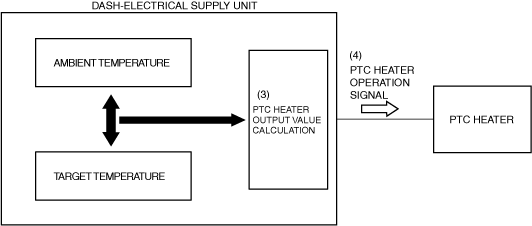
3. The PTC heater operation determination calculates (3) the PTC heater output value (generation amount and operation time) based on the ambient temperature and target temperature.
am3zzn00008443
|
4. The dash-electrical supply unit outputs (4) a PTC heater operation signal based on the calculated PTC heater output value.