am3zzn00010839
|
MANUAL AIR CONDITIONER SYSTEM [MANUAL AIR CONDITIONER (E)]
id0740a20062y4
Outline
Function
am3zzn00010839
|
am3zzn00010840
|
Airflow temperature control
Airflow volume control
Airflow mode control
Air intake control
A/C compressor control
Air conditioner i-stop control
am3zzn00010841
|
Structure/construction
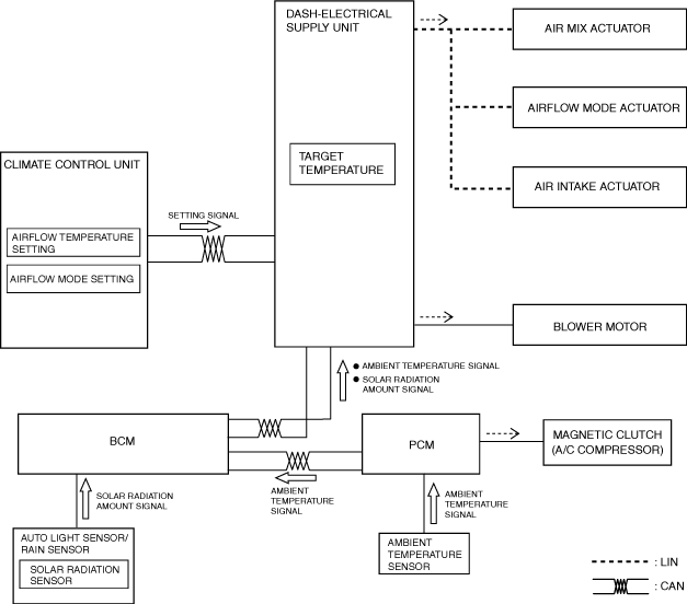
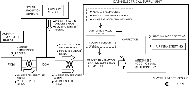
Block diagram
am3zzn00010842
|
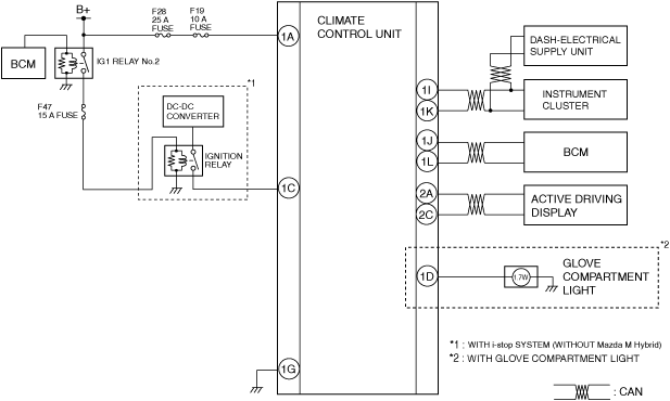
System wiring diagram
am3zzn00010364
|
am3zzn00010063
|
am3zzn00010368
|
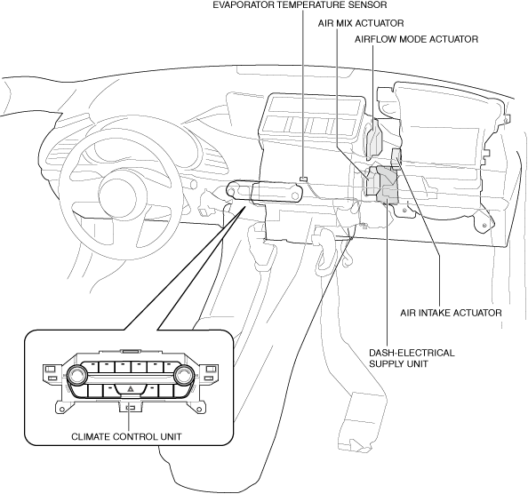
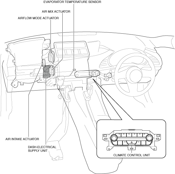
Structural view (interior L.H.D.)
am3zzn00009036
|
Structural view (interior R.H.D.)
am3zzn00009037
|
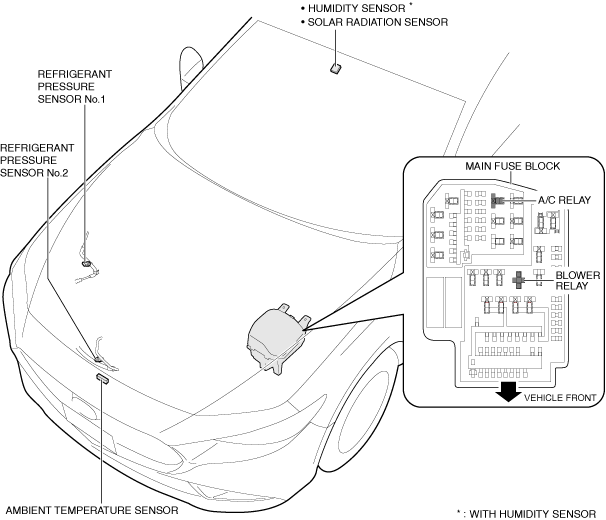
Structural view (exterior)
am3zzn00009038
|
Operation
Airflow temperature control
1. When the airflow temperature setting dial is operated with the ignition switched ON (engine off or on), the climate control unit sends an airflow temperature setting signal (1) to the dash-electrical supply unit.
2. Based on the signals (2) from each sensor which changes according to the airflow temperature setting and the vehicle conditions, the dash-electrical supply unit performs airflow temperature determination (3).
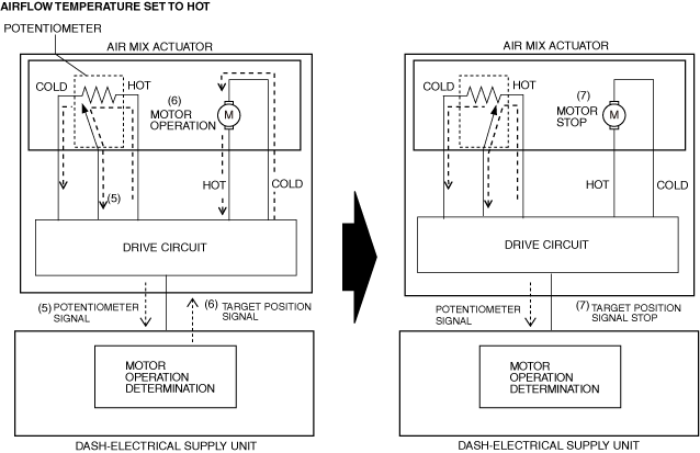
3. The dash-electrical supply unit operates (4) the air mix actuator based on the results of the airflow temperature determination and corrections.
am3zzn00010843
|
4. The air mix actuator sends a potentiometer signal (5) to the dash-electrical supply unit.
5. The dash-electrical supply unit detects the current actuator opening angle based on the potentiometer signal.
6. When the potentiometer signal differs from the target actuator opening angle, the dash-electrical supply unit outputs a target position signal (6).
7. When the potentiometer signal is equal to the target actuator opening angle, the dash-electrical supply unit stops (7) output of the target position signal.
am3zzn00009040
|
Airflow volume control
1. When IG1 relay No.2 turns ON, the blower relay turns ON (1).
2. When the airflow volume setting switch is operated, the climate control unit sends an airflow volume setting signal (2) to the dash-electrical supply unit.
3. Based on the airflow volume setting and the signals (3) from each sensor, the dash-electrical supply unit performs airflow volume determination (4).
4. The dash-electrical supply unit controls the blower fan controller (5) and changes the airflow volume (blower motor applied voltage) based on the results of the airflow volume determination and corrections.
5. The blower motor (6) changes the rotation speed according to the blower fan controller control.
am3zzn00010844
|
Airflow mode control
1. When the airflow mode switch is operated with the ignition switched ON (engine off or on), the climate control unit sends an airflow mode setting signal (1) to the dash-electrical supply unit.
2. Based on the signals (2) from each sensor which changes according to the airflow mode setting and the vehicle conditions, the dash-electrical supply unit performs airflow mode determination (3).
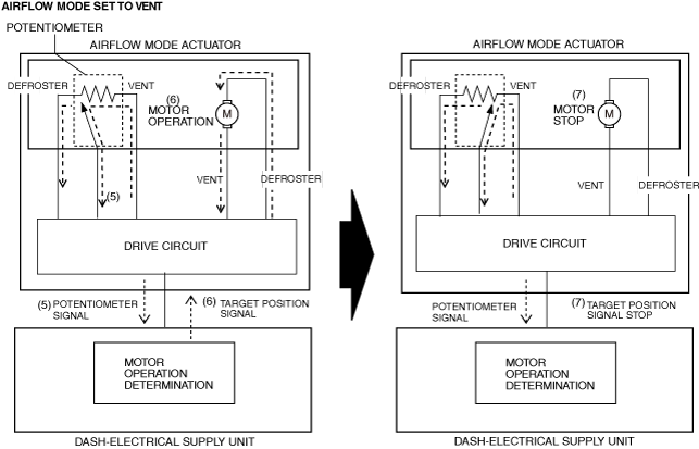
3. The dash-electrical supply unit operates (4) the airflow mode actuator based on the results of the airflow temperature determination and corrections.
am3zzn00010845
|
4. The airflow mode actuator sends a potentiometer signal (5) to the dash-electrical supply unit.
5. The dash-electrical supply unit detects the current actuator opening angle based on the potentiometer signal.
6. When the potentiometer signal differs from the target actuator opening angle, the dash-electrical supply unit outputs a target position signal (6).
7. When the potentiometer signal is equal to the target actuator opening angle, the dash-electrical supply unit stops (7) output of the target position signal.
am3zzn00009043
|
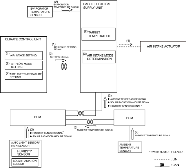
Air intake control
1. When the air intake setting switch is operated with the ignition switched ON (engine off or on), the climate control unit sends an air intake setting signal (1) to the dash-electrical supply unit.
2. Based on the signals (2) from each sensor which changes according to the air intake setting and the vehicle conditions, the dash-electrical supply unit performs air intake mode determination (3).
3. The dash-electrical supply unit operates (4) the air intake actuator based on the results of the air intake mode determination and corrections.
am3zzn00010846
|
4. The air intake actuator sends a potentiometer signal (5) to the dash-electrical supply unit.
5. The dash-electrical supply unit detects the current actuator opening angle based on the potentiometer signal.
6. When the potentiometer signal differs from the target actuator opening angle, the dash-electrical supply unit outputs a target position signal (6).
7. When the potentiometer signal is equal to the target actuator opening angle, the dash-electrical supply unit stops (7) output of the target position signal.
am3zzn00009045
|
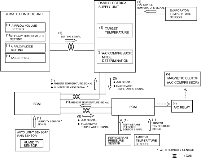
A/C compressor control
1. Based on the signals (1) from each sensor which changes according to the A/C setting and the vehicle conditions, the dash-electrical supply unit performs A/C compressor mode determination (2).
2. The dash-electrical supply unit sends (3) an A/C signal to the PCM based on the results of the A/C compressor mode determination and corrections.
3. The PCM turns the A/C relay on (4) based on the A/C signal and the signals from each sensor which change according to the vehicle conditions.
4. When the A/C relay turns on, the magnetic clutch turns on (5).
am3zzn00010847
|
Air conditioner i-stop control
|
Item |
Condition |
|---|---|
|
Ambient temperature
|
Ambient temperature is -10 °C {14 °F} or below, or 50 °C {122 °F} or more
|
|
Blower motor control
|
Blower motor is operated when speed is set to 1 or higher
|
|
Mode control
|
During manual defroster control
|
|
Temperature setting and compressor control
|
During MAX HOT or MAX COLD and A/C ON
|
|
Air conditioner control
|
Target temperature not controlled (comfortable cabin temperature not controlled)
|