|
1
|
VERIFY BCM DTCs
• Perform the DTC inspection for the BCM using the M-MDS.
• Is a DTC detected?
|
Yes
|
Perform the applicable DTC troubleshooting.
|
|
No
|
Go to the next step.
|
|
2
|
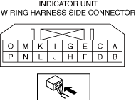
INSPECT INDICATOR UNIT CONNECTOR CONDITION
• Switch the ignition off.
• Disconnect the negative battery terminal.
• Disconnect the indicator unit connector.
• Inspect the connector engagement and connection condition and inspect the terminals for damage, deformation, corrosion, or disconnection.
• Is there any malfunction of the indicator unit connector?
|
Yes
|
Replace the malfunctioning part and perform the repair completion verification.
|
|
No
|
Go to the next step.
|
|
3
|
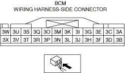
INSPECT BCM CONNECTOR CONDITION
• Disconnect the BCM connector.
• Inspect the connector engagement and connection condition and inspect the terminals for damage, deformation, corrosion, or disconnection.
• Is the connector normal?
|
Yes
|
Go to the next step.
|
|
No
|
Replace the malfunctioning part and perform the repair completion verification.
|
|
4
|
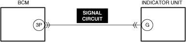
INSPECT SEAT PAD OFF INDICATOR CIRCUIT FOR SHORT TO GROUND
• Indicator unit and BCM connectors are disconnected.
• Inspect the PAD OFF indicator circuit for short to ground.
-
Note
-
• Inspect for a short to ground while shaking the wiring harness between the indicator unit and BCM.
• Is the circuit normal?
|
Yes
|
Go to the next step.
|
|
No
|
Repair or replace the malfunctioning location and perform the repair completion verification.
|
|
5
|
INSPECT PAD OFF INDICATOR CIRCUIT FOR OPEN CIRCUIT
• Indicator unit and BCM connectors are disconnected.
• Inspect the PAD OFF indicator circuit for open circuit.
-
Note
-
• Inspect for open circuit while shaking the wiring harness between the indicator unit and BCM.
• Is the circuit normal?
|
Yes
|
Go to the next step.
|
|
No
|
Repair or replace the malfunctioning location and perform the repair completion verification.
|
|
6
|
INSPECT PAD OFF INDICATOR CIRCUIT FOR SHORT TO POWER SUPPLY
• Indicator unit and BCM connectors are disconnected.
• Connect the negative battery terminal.
• Switch the ignition ON (engine off or on).
• Inspect the PAD OFF indicator circuit for a short to power supply.
-
Note
-
• Inspect for a short to power supply while shaking the wiring harness between the indicator unit and BCM.
• Is the circuit normal?
|
Yes
|
Go to the next step.
|
|
No
|
Repair or replace the malfunctioning location and perform the repair completion verification.
|
|
7
|
INSPECT INDICATOR UNIT
• Inspect the indicator unit.
• Is it normal?
|
Yes
|
Perform the repair completion verification.
|
|
No
|
Replace the indicator unit and perform the repair completion verification.
|
|
Repair completion verification
|
PERFORM SAS CONTROL MODULE DTC INSPECTION
• Reconnect all disconnected connectors.
• Connect the negative battery terminal.
• Switch the ignition ON (engine off or on).
• Clear the DTC for the SAS control module using the M-MDS.
• Perform the DTC inspection for the SAS control module using the M-MDS.
• Are the same Pending DTCs present?
|
Yes
|
Refer to the controller area network (CAN) malfunction diagnosis flow to inspect for a CAN communication error.
If the CAN communication is normal, perform the diagnosis from Step 1.
• If the malfunction recurs, replace the SAS control module.
|
|
No
|
DTC troubleshooting completed.
|