DOOR LOCK DOES NOT OPERATE [SECURITY AND LOCKS (E)]


id0903k70229kb


Outline

Description
•  All doors cannot be locked/unlocked using the door lock switch.
•  All doors cannot be locked/unlocked using the auto door lock.
Possible cause
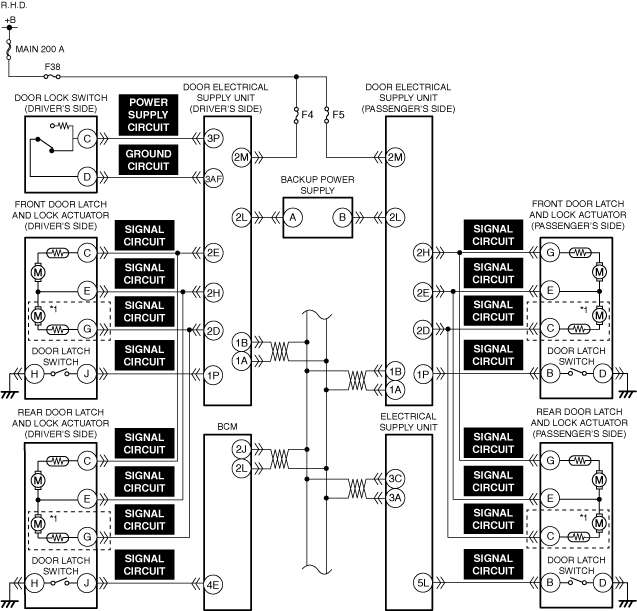
•  Connector or terminal malfunction of the following parts:
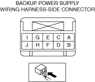
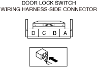
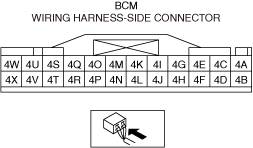
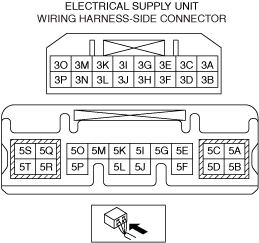
―  Door lock switch
―  Front door latch and lock actuator
―  Rear door latch and lock actuator
―  BCM
―  Electrical Supply Unit
―  Door-electrical supply unit
―  Backup power supply
•  Backup power supply malfunction
•  Short to ground or open circuit in door lock switch power supply circuit
•  Open circuit in door lock switch ground circuit
•  Short to ground or open circuit in door lock actuator (front door latch and lock actuator) signal circuit
•  Short to ground or open circuit in door latch switch (front door latch and lock actuator) signal circuit
•  Short to ground or open circuit in door lock actuator (rear door latch and lock actuator) signal circuit
•  Short to ground or open circuit in door latch switch (rear door latch and lock actuator) signal circuit
•  Door lock switch malfunction
•  Front door latch and lock actuator malfunction
•  Rear door latch and lock actuator malfunction
•  Door-electrical supply unit malfunction

*1  :With double locking system

Diagnostic Procedure

Step

Inspection

Results

Action

1
VERIFY ALL SYSTEM DTCs
•  Perform the DTC inspection.
•  Are any DTCs displayed?
Yes
Repair the malfunctioning location according to the applicable DTC troubleshooting.
No
Go to the next step.
2
INSPECT DOOR LOCK SWITCH, FRONT DOOR LATCH AND LOCK ACTUATOR, REAR DOOR LATCH AND LOCK ACTUATOR, BCM, ELECTRICAL SUPPLY UNIT, DOOR-ELECTRICAL SUPPLY UNIT, AND BACKUP POWER SUPPLY CONNECTORS FOR MALFUNCTION
•  Inspect the applicable connector and terminal.
•  Are the connector and terminal normal?
Yes
Go to the next step.
No
Repair or replace the malfunctioning location and perform the repair completion verification.
3
INSPECT BACKUP POWER SUPPLY FOR MALFUNCTION
•  Inspect the applicable part.
•  Is the part normal?
Yes
Go to the next step.
No
Repair or replace the malfunctioning location and perform the repair completion verification.
4
INSPECT DOOR LOCK SWITCH POWER SUPPLY CIRCUIT FOR SHORT TO GROUND AND OPEN CIRCUIT
•  Inspect the power supply circuit for a short to ground and open circuit.
•  Is the circuit normal?
Yes
Go to the next step.
No
Repair or replace the malfunctioning location and perform the repair completion verification.
5
INSPECT DOOR LOCK SWITCH GROUND CIRCUIT FOR OPEN CIRCUIT
•  Inspect the ground circuit for open circuit.
•  Is the circuit normal?
Yes
Go to the next step.
No
Repair or replace the malfunctioning location and perform the repair completion verification.
6
INSPECT DOOR LATCH AND LOCK ACTUATOR SIGNAL CIRCUIT FOR SHORT TO GROUND AND OPEN CIRCUIT
•  Inspect the signal circuit for open circuit.
•  Is the circuit normal?
Yes
Go to the next step.
No
Repair or replace the malfunctioning location and perform the repair completion verification.
7
INSPECT DOOR LOCK SWITCH FOR MALFUNCTION
•  Inspect the applicable part.
•  Is the part normal?
Yes
Go to the next step.
No
Repair or replace the malfunctioning location and perform the repair completion verification.
8
INSPECT DOOR LATCH AND LOCK ACTUATOR FOR MALFUNCTION
•  Is the part normal?
Yes
Go to the next step.
No
Repair or replace the malfunctioning location and perform the repair completion verification.
Repair completion verification
VERIFY THAT VEHICLE IS REPAIRED
•  Install/connect the part removed/disconnected during the troubleshooting procedure.
•  Has the malfunction symptom been eliminated?
Yes
Complete the symptom troubleshooting. (Explain contents of repair to customer)
No
Refer to the controller area network (CAN) malfunction diagnosis flow to inspect for a CAN communication error.
If the CAN communication is normal, perform the diagnosis from Step 1.
•  If the malfunction is not resolved, replace the door-electrical supply unit.