Note
REAR OUTER HANDLE REMOVAL/INSTALLATION
id091400510200
TYPE A
1. Fully close the rear door glass.
2. Disconnect the negative battery terminal. (See NEGATIVE BATTERY TERMINAL DISCONNECTION/CONNECTION [(E)].)
3. Remove the following parts:
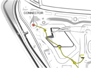
4. Disconnect the connector.
am3zzw00022084
|
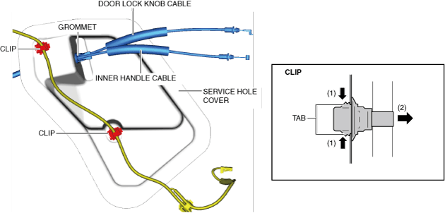
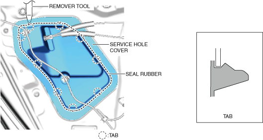
5. Detach the service hole cover tabs from the body using a remover tool.
am3zzw00031265
|
6. Remove the clips.
am3zzw00022086
|
7. Remove the grommet.
8. Pull the door lock knob cable and the inner handle cable from the service hole cover.
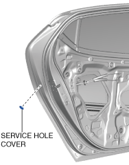
9. Remove the service hole cover. (See Service hole cover installation note.)
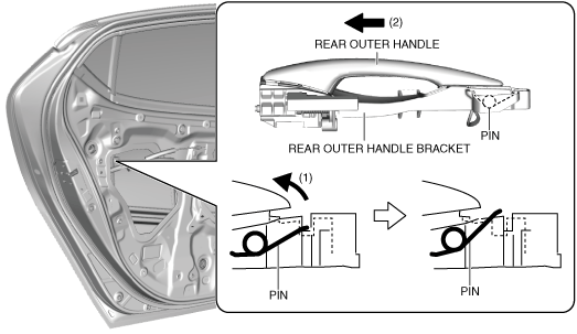
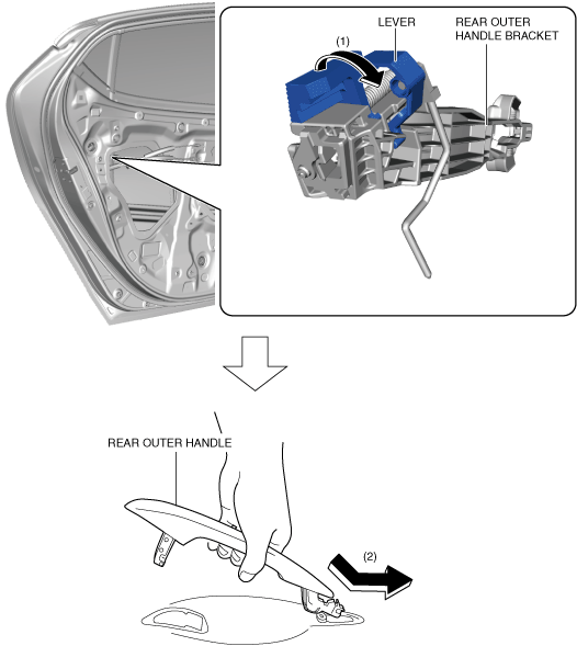
10. While pressing the rear outer handle bracket pin in the direction of arrow (1) shown in the figure, pull the rear outer handle in the direction of arrow (2) and detach the rear outer handle bracket pin from the rear outer handle.
am3zzw00022090
|
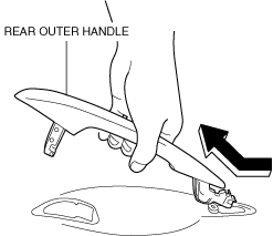
11. Remove the rear outer handle in the direction of the arrow shown in the figure. (See Rear outer handle installation note.)
am3zzw00022091
|
12. Remove the service hole cover.
am3zzw00022087
|
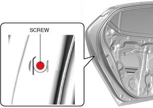
13. Loosen the screw.
am3zzw00022088
|
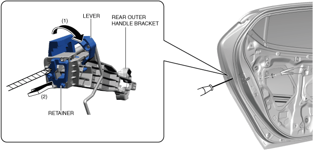
14. While moving the lever in the direction of arrow (1) shown in the figure, press the retainer in the direction of arrow (2) using a tape-wrapped screwdriver, and then secure the lever.
am3zzw00036830
|
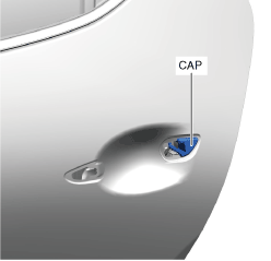
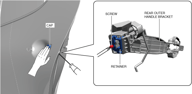
15. Remove the cap. (See Cap installation note.)
am3zzw00036831
|
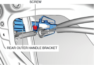
16. Loosen the screw securing the rear outer handle bracket.
am3zzw00022092
|
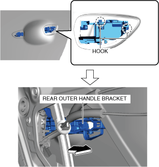
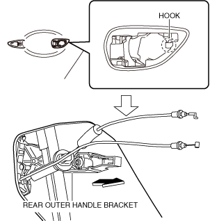
17. Pull the rear outer handle bracket in the direction of the arrow shown in the figure and detach the rear outer handle bracket hook from the body.
am3zzw00028597
|
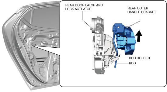
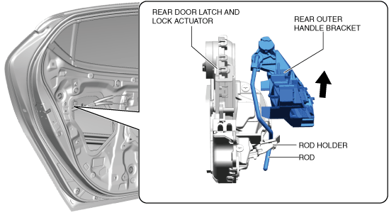
18. Lift the rear outer handle bracket in the direction of the arrow shown in the figure and pull out the rod from the rod holder. (See Rear outer handle bracket installation note.)
am3zzw00022094
|
19. Remove the rear outer handle bracket.
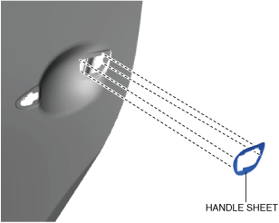
20. Remove the handle sheet from the body.
am3zzw00029696
|
21. Install in the reverse order of removal.
Cap installation note
am3zzw00036832
|
Rear outer handle installation note
am3zzw00022096
|
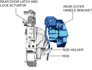
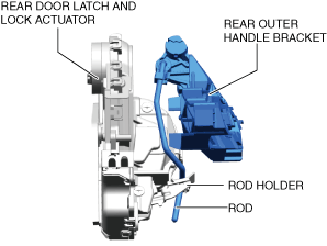
Rear outer handle bracket installation note
am3zzw00022097
|
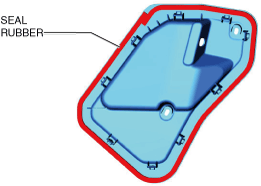
Service hole cover installation note
am3zzw00031178
|
TYPE B
1. Fully close the rear door glass.
2. Disconnect the negative battery terminal. (See NEGATIVE BATTERY TERMINAL DISCONNECTION/CONNECTION [(E)].)
3. Remove the following parts:
4. Disconnect the connector.
am3zzw00038558
|
5. Detach the service hole cover tabs from the body using a remover tool.
am3zzw00038559
|
6. Remove the clips.
am3zzw00038560
|
7. Remove the grommet.
8. Pull the door lock knob cable and the inner handle cable from the service hole cover.
9. Remove the service hole cover. (See Service hole cover installation note.)
10. Remove the service hole cover.
am3zzw00038561
|
11. Loosen the screw.
am3zzw00038562
|
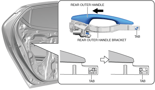
12. Pull the rear outer handle in the direction of the arrow shown in the figure, and detach the rear outer handle bracket tab from the rear outer handle.
am3zzw00038563
|
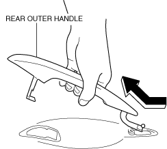
13. Remove the rear outer handle in the direction of the arrow shown in the figure.
am3zzw00038564
|
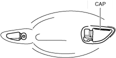
14. Remove the cap.
am3zzw00038565
|
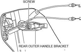
15. Loosen the screw securing the rear outer handle bracket.
am3zzw00038566
|
16. Pull the rear outer handle bracket in the direction of the arrow shown in the figure and detach the rear outer handle bracket hook from the body.
am3zzw00038567
|
17. Lift the rear outer handle bracket in the direction of the arrow shown in the figure and pull out the rod from the rod holder. (See Rear outer handle bracket installation note.)
am3zzw00038568
|
18. Remove the rear outer handle bracket.
19. Remove the handle sheet from the body.
am3zzw00038569
|
20. Install in the reverse order of removal.
Rear outer handle bracket installation note
am3zzw00038570
|
Service hole cover installation note
am3zzw00038571
|