|
am3zzn00008811
DAYTIME RUNNING LIGHT (DRL) SYSTEM
id091800015200
Outline
Function
|
Vehicle speed |
Ignition switch |
Parking brake |
Selector lever position (ATX) |
Light switch position |
Dimmer switch position |
Auto light system |
Daytime running light (DRL) |
|---|---|---|---|---|---|---|---|
|
3 km/h {2 mph} or more
|
ON (engine on)
|
Release
|
Except P position
|
OFF
|
HI
|
—
|
On
|
|
LO
|
On
|
||||||
|
FLASH-TO-PASS
|
Off
|
||||||
|
AUTO
|
HI
|
Off
|
On
|
||||
|
On
|
Off
|
||||||
|
LO
|
Off
|
On
|
|||||
|
On
|
Off
|
||||||
|
FLASH-TO-PASS
|
Off
|
Off
|
|||||
|
On
|
Off
|
||||||
|
TNS (parking lights)
|
HI
|
—
|
On
|
||||
|
LO
|
On
|
||||||
|
FLASH-TO-PASS
|
Off
|
||||||
|
HEAD
|
HI
|
—
|
Off
|
||||
|
LO
|
Off
|
||||||
|
FLASH-TO-PASS
|
Off
|
Personalization features (except canada specs.)
Structure/Construction
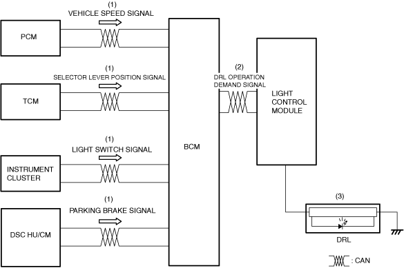
System structure
am3zzn00008811
|
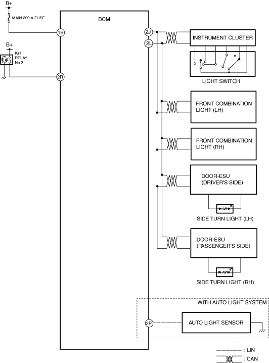
System wiring diagram
am3zzn00010688
|
Operation
Operation conditions
Operation
1. When the operation conditions are met (1),BCM transmits DRL operation demand signal to Light Control Module. (2).
2. When the Light Control Module the daytime running light (DRL) is illuminated (3).
am3zzn00010689
|