WARNING/INDICATION/ALARM [LIGHTING SYSTEMS]
id0918001305z8
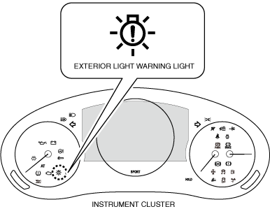
EXTERIOR LIGHT WARNING LIGHT
Purpose
• The exterior light warning light notifies the driver the following conditions:
-
― Headlight auto leveling system non-initialization
― Headlight auto leveling system malfunction
― Adaptive front lighting system (AFS) malfunction (with adaptive front lighting system (AFS))
― Exterior light malfunction
Function
• The instrument cluster turns on/flashes the exterior light warning light based on the following signals:
|
Signal name
|
Sending module/part name
|
Communication method
|
Exterior light warning light operation status
|
|
Headlight auto leveling system non-initialization signal
|
Auto leveling control module/AFS control module
|
CAN
|
Flash
|
|
• Headlight auto leveling system malfunction signal
• Adaptive front lighting system (AFS) malfunction signal (with adaptive front lighting system (AFS))
• LED headlight malfunction signal
|
On
|
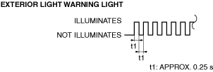
• The flash pattern of the exterior light warning light is as shown in the figure.
Structure/Construction
• The exterior light warning light is built into the instrument cluster.
• A warning message in the center display is displayed when the exterior light warning light is turned on. For the message content and verification method, refer to the [CENTER DISPLAY] in the workshop manual.
Operation
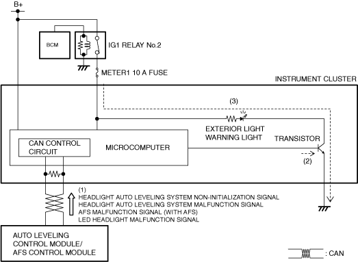
1. When the adaptive front lighting system (AFS) control module detects a malfunction with the ignition switched ON (engine off or on), it sends (1) any of the following signals to the instrument cluster via CAN communication.
-
― Headlight auto leveling system non-initialization signal
― Headlight auto leveling system malfunction signal
― Adaptive front lighting system (AFS) malfunction signal (with adaptive front lighting system (AFS))
― LED headlight malfunction signal
2. The instrument cluster turns the transistor on (2) based on each signal.
3. When the transistor turns on intermittently, the exterior light warning light flashes (3), and when the transistor is on continuously, the exterior light warning light turns on (3).
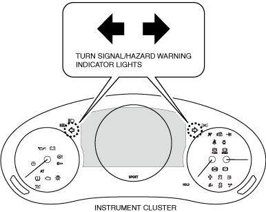
TURN SIGNAL/HAZARD WARNING INDICATOR LIGHTS
Purpose
• The turn signal/hazard warning indicator lights notify the driver that the turn lights are flashing.
Function
• When the instrument cluster receives a turn signal or hazard warning indicator signal sent from the BCM via CAN communication, it flashes the turn signal/hazard warning indicator lights.
-
Note
-
• If a turn light is burned out, the turn signal/hazard warning indicator lights flashing speed increases.
Structure/Construction
• The turn signal/hazard warning indicator lights are built into the instrument cluster.
Operation
Turn light system
-
1. When the turn switch is in the LH or RH position, the instrument cluster sends (1) a turn switch LH signal or turn switch RH signal to the body control module (BCM) via CAN communication.
2. When the body control module (BCM) receives the turn switch LH signal or turn switch RH signal with the ignition switched ON (engine off or on), it sends (2) the signal to the instrument cluster as a turn signal.
3. The instrument cluster turns the transistor on (3) intermittently based on the turn signal.
4. When the transistor turns on intermittently, the turn signal indicator light flashes (4).
Hazard warning system
-
1. When the hazard warning switch turns on, the climate control unit sends (1) a turn switch LH signal and turn switch RH signal to the body control module (BCM) via CAN communication.
2. When the body control module (BCM) receives the turn switch LH signal and turn switch RH signal, it sends (2) the signal to the instrument cluster as a hazard warning indicator signal.
3. The instrument cluster turns the transistor on (3) intermittently based on the hazard warning indicator signal.
4. When the transistor turns on intermittently, the hazard warning indicator light flashes (4).
LIGHTS-ON INDICATOR LIGHT
Purpose
• The lights-on indicator light notifies the driver that the TNS (parking lights) is turned on.
Function
• When the instrument cluster receives the TNS (parking lights) signal sent from the BCM via CAN communication, it turns the lights-on indicator light on.
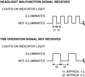
• The instrument cluster flashes the lights-on indicator light when it receives a headlight malfunction signal from the BCM or when the TNS (parking lights) operation signal cannot be received for a specified time.
• The lights-on indicator light flashes in the pattern shown in the figure.
Structure/Construction
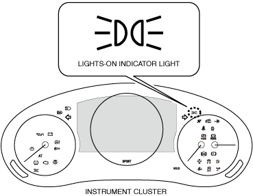
• The lights-on indicator light is built into the instrument cluster.
Operation
Light switch operation
-
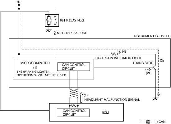
1. When the light switch is in the TNS position, the instrument cluster sends (1) a TNS signal to the body control module (BCM) via CAN communication.
2. The body control module (BCM) sends (2) a TNS on signal to the instrument cluster.
3. The instrument cluster turns the transistor on (3) based on the TNS on signal.
4. When the transistor turns on, a ground circuit with the lights-on indicator light is established and the lights-on indicator light turns on (4).
HEADLIGHT HIGH-BEAM INDICATOR LIGHT
Purpose
• The headlight high-beam indicator light notifies the driver that the headlights HI are turned on.
Function
• When the instrument cluster receives the headlight HI signal or FLASH-TO-PASS signal sent from the BCM (
) via CAN communication, it turns the headlight high-beam indicator light on.
Structure/Construction
• The headlight high-beam indicator light is built into the instrument cluster.
Operation
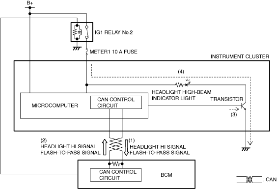
1. When the light switch is in any of the following positions, the instrument cluster sends (1) a headlight HI signal or passing signal to the body control module (BCM) via CAN communication.
-
― Light switch at HEAD position and dimmer switch at HI position
― Dimmer switch at passing position
2. When the BCM receives the headlight HI signal or FLASH-TO-PASS signal with the ignition switched ON (engine off or on), it sends (2) a headlight HI signal or FLASH-TO-PASS signal to the instrument cluster.
3. The instrument cluster turns the transistor on (3) based on the headlight HI on signal or passing on signal.
4. When the transistor turns on, a ground circuit with the headlight high-beam indicator light is established, and the headlight high-beam indicator light turns on (4).