 |
am3zzn00008882
REAR WIPER/WASHER SYSTEM
id091900002000
Outline
Function
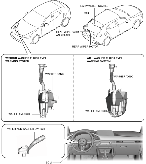
Structure/Construction
System structure
am3zzn00008882
|
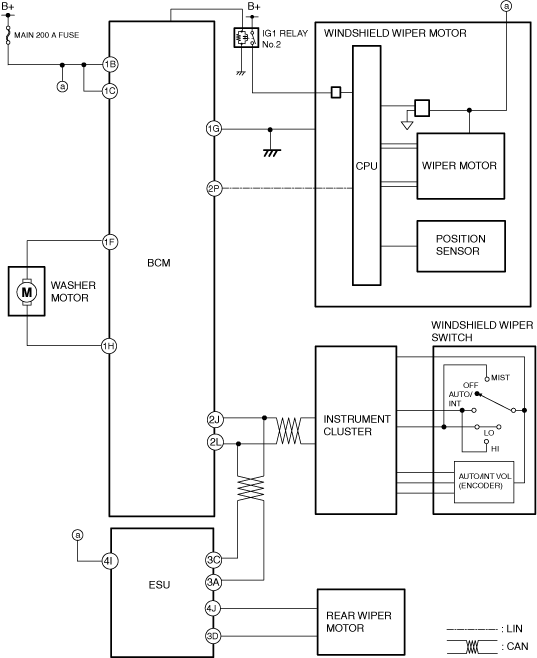
System wiring diagram
ac30zn00000592
|
Operation
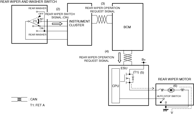
Continuous wiper operation
1. When the rear wiper and washer switch is in the on position (1), the instrument cluster detects (2) a rear wiper switch on signal.
2. The instrument cluster sends (3) the rear wiper switch on signal to the body control module (BCM) via CAN communication.
3. When the body control module (BCM) receives the rear wiper switch on signal, it sends (4) a rear wiper operation request signal to the electrical supply unit (ESU) via CAN communication.
4. When the electrical supply unit (ESU) receives the rear wiper operation request signal, it turns FET A on (5).
5. When FET A turns on, the rear wiper operates (6) continuously.
ac30zn00000593
|
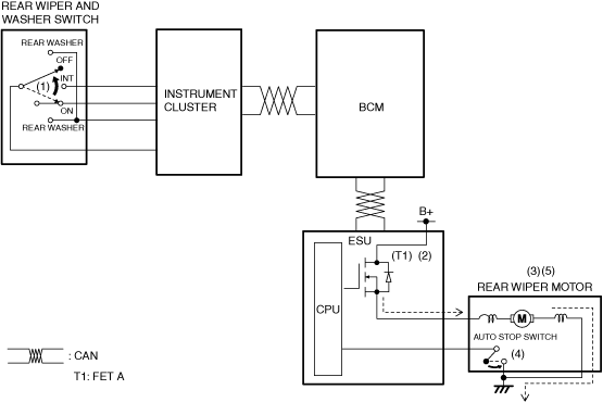
Auto-stop operation
ac30zn00000594
|
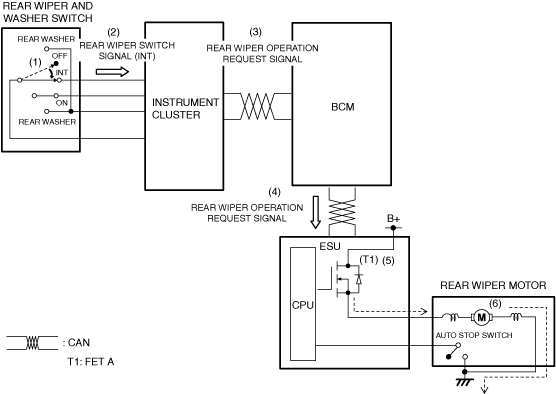
Intermittent wiper operation
1. When the rear wiper and washer switch is in the INT position (1), the instrument cluster detects (2) a rear wiper switch INT signal.
2. The instrument cluster sends (3) the rear wiper switch INT signal to the body control module (BCM) via CAN communication.
3. When the body control module (BCM) receives the rear wiper switch INT signal, it sends (4) a rear wiper operation request signal to the electrical supply unit (ESU) via CAN communication.
4. When the electrical supply unit (ESU) receives the rear wiper operation request signal, it turns FET A on (5).
5. When FET A turns on, the rear wiper performs intermittent wiper operation (6).
ac30zn00000595
|
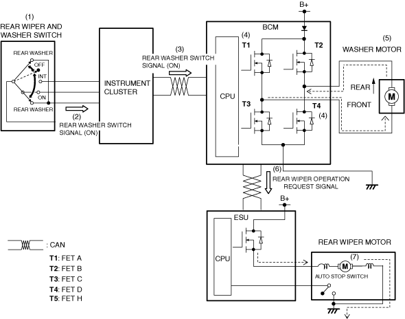
Synchronized washer operation
1. When the rear wiper and washer switch is in the rear washer position (1) with the ignition switched ON (engine off or on), the instrument cluster detects (2) a rear washer switch on signal.
2. The instrument cluster sends (3) the rear washer switch on signal to the body control module (BCM) via CAN communication.
3. When the body control module (BCM) receives the rear washer switch on signal, it turns FET A and FET D on (4) and operates (5) the rear washer motor.
4. When the body control module (BCM) receives the rear washer switch on signal for a certain period of time, it sends (6) a rear wiper operation request signal to the electrical supply unit (ESU) via CAN communication.
5. When the electrical supply unit (ESU) receives the rear wiper operation request signal, it operates (7) the rear wiper.
6. When the rear washer switch is in the off position, the rear wiper stops after it operated twice.
ac30zn00000596
|