MULTIPLEX COMMUNICATION SYSTEM [(E)]


id1000000014x2


Outline

•  A control area network (CAN) system has been adopted in which the multiple control modules send/receive signals using two common communication lines.
ac5uun00002862
•  Local CAN, ISO communication, or LIN communication has been adopted for the individual communication between control modules in consideration of the communication speed and the cost.

System Wiring Diagram

Note
•  The following figure shows the CAN/LIN communication/ISO communication/local CAN connection conditions. The availability of the equipment may differ depending on the vehicle specifications.

CAN communication

am3zzn00009595

Local CAN

am3zzn00007934

LIN communication

am3zzn00009309

ISO communication

am3zzn00007936

Structural View

Note
•  The following figure shows the installation positions for the equipment which perform CAN communication. The availability of the equipment may differ depending on the vehicle specifications.

L.H.D.

am3zzn00009310
am3zzn00009311

R.H.D.

am3zzn00009312
am3zzn00009313

Function


CAN (controller area network) system

•  CAN BUS No.1 is used for communication between the following modules:
―  Body control module (BCM)
―  EPS control module
―  Adaptive front lighting system (AFS) control module/auto leveling control module/adaptive led headlights control module/a
―  SAS control module
―  Electronically controlled brake unit/DSC HU/CM
―  TCM
―  PCM
•  CAN BUS No.2 is used for communication between the following modules:
―  Body control module (BCM)
―  NOx sensor
―  PM sensor
―  Mazda M Hybrid battery
―  Electronically controlled brake unit/DSC HU/CM
―  DC-DC converter (Mazda M Hybrid)
―  Integrated starter generator (ISG)
―  PCM
•  CAN BUS No.3 is used for communication between the following modules:
―  Body control module (BCM)
―  Front combination light (LH)
―  Front combination light (RH)
―  Climate control unit
―  Active driving display
―  Steering lock unit
―  Steering angle sensor
―  Instrument cluster
―  Door-electrical supply unit (driver's side)
―  Door-electrical supply unit (passenger's side)
―  LF control unit
―  Dash-electrical supply unit
―  Shift panel (indicator)
―  Electrical supply unit (ESU)
•  CAN BUS No.4 is used for communication between the following modules:
―  Body control module (BCM)
―  Rear side radar sensor (RH)
―  Parking assist unit (ultrasonic)
―  Electrical supply unit (ESU)
•  CAN BUS No.5 is used for communication between the following modules:
―  Body control module (BCM)
―  Parking assist unit (optical)/360° view monitor control module
―  Driver monitoring camera unit
―  Forward sensing camera (FSC)
•  CAN BUS No.6 is used for communication between the following modules:
―  Body control module (BCM)
―  Front side radar sensor (LH)
―  Front radar sensor
•  CAN BUS No.7 is used for communication between the following modules:
―  Body control module (BCM)
―  Audio amplifier
―  Connectivity master unit (CMU) (Except Chinese specs.)/Audio control unit(ACU) (Chinese specs.)
•  CAN BUS No.8 is used for communication between the following modules:
―  Body control module (BCM)
―  Emergency call unit


Local CAN

•  Local CAN is used for communication between the following modules:
―  Between PCM and TCM
―  Between front side radar sensor (LH) and front side radar sensor (RH)
―  Between rear side radar sensor (LH) and rear side radar sensor (RH)


LIN communication

•  LIN communication is used for communication between the following modules:
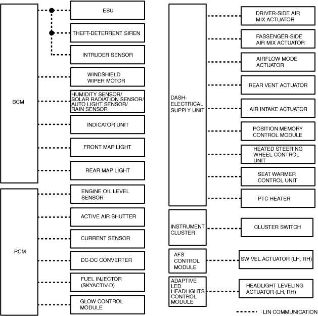
―  Between body control module (BCM) and electrical supply unit (ESU)
―  Between body control module (BCM) and theft-deterrent siren
―  Between body control module (BCM) and intruder sensor
―  Between body control module (BCM) and windshield wiper motor
―  Between body control module (BCM) and humidity sensor/solar radiation sensor/auto light sensor/rain sensor
―  Between body control module (BCM) and indicator unit
―  Between body control module (BCM) and front map light
―  Between body control module (BCM) and rear map light
―  Between electrical supply unit (ESU) and theft-deterrent siren
―  Between electrical supply unit (ESU) and intruder sensor
―  Between dash-electrical supply unit and driver-side air mix actuator
―  Between dash-electrical supply unit and passenger-side air mix actuator
―  Between dash-electrical supply unit and airflow mode actuator
―  Between dash-electrical supply unit and rear vent actuator
―  Between dash-electrical supply unit and air intake actuator
―  Between dash-electrical supply unit and heated steering wheel control unit
―  Between dash-electrical supply unit and position memory control module
―  Between dash-electrical supply unit and seat warmer control unit
―  Between dash-electrical supply unit and PTC heater
―  Between PCM and current sensor
―  Between PCM and engine oil level sensor
―  Between PCM and active air shutter
―  Between PCM and DC-DC converter
―  Between PCM and fuel injector No.1 (SKYACTIV-G or SKYACTIV-X)
―  Between PCM and fuel injector No.2 (SKYACTIV-G or SKYACTIV-X)
―  Between PCM and fuel injector No.3 (SKYACTIV-G or SKYACTIV-X)
―  Between PCM and fuel injector No.4 (SKYACTIV-G or SKYACTIV-X)
―  Between PCM and glow control module
―  Between adaptive front lighting system (AFS) control module and swivel actuator (LH)
―  Between adaptive front lighting system (AFS) control module and swivel actuator (RH)
―  Between adaptive LED headlights control module and headlight leveling actuator (LH)
―  Between adaptive LED headlights control module and headlight leveling actuator (RH)
―  Between instrument cluster and cluster switch


ISO communication

•  ISO communication is used for communication between the following modules:
―  Between body control module (BCM) and LF control unit
―  Between body control module (BCM) and remote engine start
―  Between connectivity master unit (CMU) (Except Chinese specs.)/audio control unit(ACU) (Chinese specs.) and commander switch


Construction


CAN

•  The CAN BUS No.1 has terminating resistors built into the following units which form the CAN lines.
―  Body control module (BCM)
―  PCM
•  The CAN BUS No.2 has terminating resistors built into the following units which form the CAN lines.
―  Body control module (BCM)
―  PCM
•  The CAN BUS No.3 has terminating resistors built into the following units which form the CAN lines.
―  Body control module (BCM)
―  Electrical supply unit (ESU)
•  The CAN BUS No.4 has terminating resistors built into the following units which form the CAN lines.
―  Body control module (BCM)
―  Electrical supply unit (ESU)
•  The CAN BUS No.5 has terminating resistors built into the following units which form the CAN lines.
―  Body control module (BCM)
―  Forward sensing camera (FSC)
•  The CAN BUS No.6 has terminating resistor built into the following units which form the CAN lines.
―  Body control module (BCM)
•  The CAN BUS No.7 has terminating resistors built into the following units which form the CAN lines.
―  Body control module (BCM)
―  Connectivity master unit (CMU) (Except Chinese specs.)/Audio control unit(ACU) (Chinese specs.)
•  The CAN BUS No.8 has terminating resistors built into the following units which form the CAN lines.
―  Body control module (BCM)
―  Emergency call unit


Local CAN

•  The local CAN has terminating resistors built into the following units which form the CAN lines.
―  PCM
―  TCM
―  Front side radar sensor (LH)
―  Front side radar sensor (RH)
―  Rear side radar sensor (LH)
―  Rear side radar sensor (RH)


LIN communication

•  The LIN communication has drivers built into the following units which form the LIN communication lines.
―  Body control module (BCM)
―  Electrical supply unit (ESU)
―  Theft-deterrent siren
―  Intruder sensor
―  Windshield wiper motor
―  Humidity sensor/solar radiation sensor/auto light sensor/rain sensor
―  Indicator unit
―  Front map light
―  Rear map light
―  Dash-electrical supply unit
―  Driver-side air mix actuator
―  Passenger-side air mix actuator
―  Airflow mode actuator
―  Rear vent actuator
―  Air intake actuator
―  Heated steering wheel control unit
―  Position memory control module
―  Seat warmer control unit
―  PTC heater
―  PCM
―  Engine oil level sensor
―  Current sensor
―  Active air shutter
―  Fuel injector No.1 (SKYACTIV-G or SKYACTIV-X)
―  Fuel injector No.2 (SKYACTIV-G or SKYACTIV-X)
―  Fuel injector No.3 (SKYACTIV-G or SKYACTIV-X)
―  Fuel injector No.4 (SKYACTIV-G or SKYACTIV-X)
―  DC-DC converter
―  Glow control module
―  Adaptive front lighting system (AFS) control module
―  Swivel actuator (LH)
―  Swivel actuator (RH)
―  Adaptive LED headlights control module
―  Headlight leveling actuator (LH)
―  Headlight leveling actuator (RH)
―  Instrument cluster
―  Cluster switch


ISO communication

•  The ISO communication has drivers built into the following units which form the ISO communication lines.
―  Body control module (BCM)
―  LF control unit
―  Remote engine start
―  Connectivity master unit (CMU)(Except Chinese specs.)/Audio control unit(ACU) (Chinese spec.)
―  Commander switch