|
1
|
DETERMINE IF MALFUNCTION CAUSE IS i-stop SYSTEM OR A/C SYSTEM
• Verify the malfunction symptom.
• Does the malfunction occur only while the i-stop function is operating (engine stopped)?
|
Yes
|
Go to the next step.
|
|
No
|
Go to the applicable A/C malfunction diagnostic procedure.
|
|
2
|
VERIFY DTC
• Perform the DTC inspection for the following modules.
-
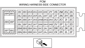
― PCM
― Dash-electrical supply unit
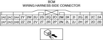
― Body control module (BCM)
• Are any DTCs displayed?
|
Yes
|
Repair the malfunctioning location according to the applicable DTC troubleshooting.
|
|
No
|
Go to the next step.
|
|
3
|
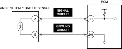
DETERMINE IF MALFUNCTION CAUSE IS AMBIENT TEMPERATURE SENSOR SIGNAL OR OTHER
• Switch the ignition ON (engine off).
• Compare the ambient temperature sensor on the multi-information display with the actual ambient temperature.
• Does the ambient temperature on the multi-information display correspond to the actual ambient temperature?
|
Yes
|
Full-auto air conditioner:
• Go to Step 6.
Manual air conditioner:
• Go to Step 9.
|
|
No
|
Go to the next step.
|
|
4
|
INSPECT AMBIENT TEMPERATURE SENSOR FOR MALFUNCTION
• Inspect the applicable part.
• Is the part normal?
|
Yes
|
Go to the next step.
|
|
No
|
Repair or replace the malfunctioning location and perform the repair completion verification 1.
|
|
5
|
INSPECT AMBIENT TEMPERATURE SENSOR SIGNAL CIRCUIT AND GROUND CIRCUIT FOR SHORT CIRCUIT AND OPEN CIRCUIT
• Inspect the applicable circuit for a short circuit and open circuit.
• Is the circuit normal?
|
Yes
|
Go to the next step.
|
|
No
|
Repair or replace the malfunctioning location and perform the repair completion verification 1.
|
|
6
|
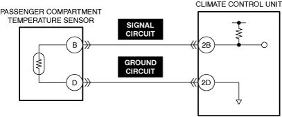
DETERMINE IF MALFUNCTION CAUSE IS PASSENGER COMPARTMENT TEMPERATURE SENSOR SIGNAL OR OTHER
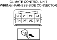
• Access the climate control unit PID AMB_TEMP_INTERNAL using the M-MDS.
• Does the AMB_TEMP_INTERNAL PID value indicate the actual cabin temperature of the vehicle?
|
Yes
|
Go to Step 9.
|
|
No
|
Go to the next step.
|
|
7
|
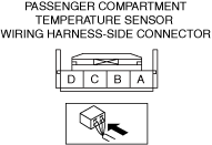
INSPECT PASSENGER COMPARTMENT TEMPERATURE SENSOR FOR MALFUNCTION
• Inspect the applicable part.
• Is the part normal?
|
Yes
|
Go to the next step.
|
|
No
|
Repair or replace the malfunctioning location and perform the repair completion verification 1.
|
|
8
|
INSPECT PASSENGER COMPARTMENT TEMPERATURE SENSOR SIGNAL CIRCUIT AND GROUND CIRCUIT FOR SHORT CIRCUIT AND OPEN CIRCUIT
• Inspect the applicable circuit for a short circuit and open circuit.
• Is the circuit normal?
|
Yes
|
Go to the next step.
|
|
No
|
Repair or replace the malfunctioning location and perform the repair completion verification 1.
|
|
9
|
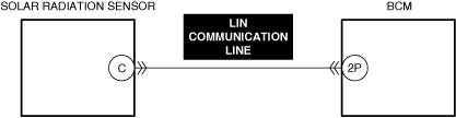
DETERMINE IF MALFUNCTION CAUSE IS SOLAR RADIATION SENSOR SIGNAL OR OTHER
• Access the dash-electrical supply unit PID SOLAR_SEN_L and SOLAR_SEN_R using the M-MDS.
• Does the SOLAR_SEN_L and SOLAR_SEN_R PID value display according to the solar radiation condition?
|
Yes
|
Go to Step 11.
|
|
No
|
Go to the next step.
|
|
10
|
INSPECT SOLAR RADIATION SENSOR LIN COMMUNICATION LINE FOR SHORT CIRCUIT AND OPEN CIRCUIT
• Inspect the applicable circuit for a short circuit and open circuit.
• Is the circuit normal?
|
Yes
|
Refer to the controller area network (CAN) malfunction diagnosis flow to inspect for a CAN communication error.
• If the CAN communication is normal, perform the diagnosis from Step 1.
-
― If the malfunction recurs, replace the solar radiation sensor and perform the repair completion verification 1.
|
|
No
|
Repair or replace the malfunctioning location and perform the repair completion verification 1.
|
|
11
|
INSPECT DRIVER-SIDE AIR MIX ACTUATOR FOR MALFUNCTION
• Inspect the applicable part.
• Is the part normal?
|
Yes
|
Inspect the air mix door and linkage for sticking.
If there is no malfunction:
• Go to the next step.
If there is any malfunction:
• Repair or replace the malfunctioning location and perform the repair completion verification 1.
|
|
No
|
Repair or replace the malfunctioning location and perform the repair completion verification 1.
|
|
Repair completion verification 1
|
VERIFY THAT VEHICLE IS REPAIRED
• Install/connect the part removed/disconnected during the troubleshooting procedure.
• Has the malfunction symptom been eliminated?
|
Yes
|
Complete the symptom troubleshooting. (Explain contents of repair to customer)
|
|
No
|
Refer to the controller area network (CAN) malfunction diagnosis flow to inspect for a CAN communication error.
• If the CAN communication is normal, perform the diagnosis from Step 1.
-
― If the malfunction recurs, go to the next step.
|
|
Repair completion verification 2
|
VERIFY IF MALFUNCTION IS CAUSED BY NOT PERFORMING PCM REPROGRAMMING
• Verify repair information and verify that there is a new calibration in the PCM.
• Is there a new calibration in the PCM?
|
Yes
|
Perform the PCM reprogramming and verify if the malfunction symptom was corrected.
• If the malfunction recurs, replace the PCM.
|
|
No
|
Replace the PCM.
|