WARNING/INDICATION/ALARM [(E)]
id1513000059a3
WARNING
Purpose
• Warning Light/Warning Indicator Light warns the driver that a malfunction is occurring in the i-ACTIVSENSE system.
Function
• The instrument cluster warning lights and power outer mirror warning indicator light turn on based on the request signal sent from the body control module (BCM) by using CAN communication.
Structure/Construction
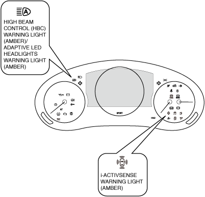
• The following warning lights (amber) turn on in the instrument cluster.
-
― i-ACTIVSENSE warning light
― High Beam Control (HBC) warning light
― Adaptive LED Headlights warning light
Operation
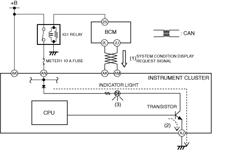
Warning Light in the instrument cluster
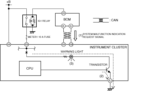
1. The instrument cluster receives (1) the system malfunction indication request signal from the body control module (BCM) by using CAN communication.
2. The instrument cluster turns the transistor on (2) based on the system malfunction indication request signal.
3. When the transistor is turned on, the warning light (amber) turns on (3).
INDICATION
Purpose
• The indication/indicator light notifies the driver of the system condition.
Function
• The instrument cluster displays the Mazda Radar Cruise Control (MRCC) standby indication based on the system condition indication request signal sent from the body control module (BCM) using CAN communication.
• The instrument cluster displays the Cruising & Traffic Support (CTS) standby indication based on the system condition indication request signal sent from the body control module (BCM) using CAN communication.
• The instrument cluster displays the Mazda Radar Cruise Control (MRCC) set indication based on the system condition indication request signal sent from the body control module (BCM) using CAN communication.
• The instrument cluster displays the Cruising & Traffic Support (CTS) set indication based on the system condition indication request signal sent from the body control module (BCM) using CAN communication.
• The instrument cluster turns on the i-ACTIVSENSE status symbol based on the i-ACTIVSENSE status symbol indication request signal sent from the body control module (BCM) using CAN communication.
• The instrument cluster turns on the high beam control (HBC) indicator light based on the system conditions display request signal sent from the body control module (BCM) using CAN communication.
• The instrument cluster turns on the adaptive LED headlights indicator light based on the system conditions display request signal sent from the body control module (BCM) using CAN communication.
• The instrument cluster turns on the Smart Brake Support (SBS) off indicator light based on the system conditions display request signal.
• The power outer mirror turns on the blind spot monitoring (BSM) warning indicator light based on the warning indication request signal.
Structure/Construction
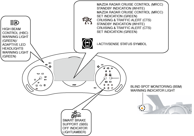
• The following indication (white) is displayed in the multi-information display.
-
― Mazda Radar Cruise Control (MRCC) standby indication
― Cruising & Traffic Support (CTS) standby indication
― i-ACTIVSENSE status symbol
• The following indication (green) is displayed in the multi-information display.
-
― Mazda Radar Cruise Control (MRCC) set indication
― Cruising & Traffic Support (CTS) set indication
― i-ACTIVSENSE status symbol
• The following indication (amber) is displayed in the multi-information display.
-
― i-ACTIVSENSE status symbol
• The following indicator light (green) turns in the instrument cluster.
-
― High Beam Control (HBC) indicator light
― Adaptive LED Headlights indicator light
• The following indicator light (amber) turns in the instrument cluster.
-
― Smart Brake Support (SBS) off indicator light
• The following warning indicator light (amber) lights up in the power outer mirror.
-
― Blind Spot Monitoring (BSM) warning indicator light
Operation
Indication in the multi-information display
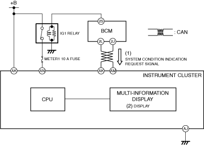
1. The instrument cluster receives (1) the system condition indication request signal from the body control module (BCM) using CAN communication.
2. The instrument cluster displays the indication (2) based on the system condition indication request signal.
Indicator Light in the instrument cluster
1. The instrument cluster receives (1) the system condition display request signal from the body control module (BCM) using CAN communication.
2. The instrument cluster turns the transistor on (2) based on the system condition display request signal.
3. When the transistor is turned on, the warning light (amber) turns on (3).
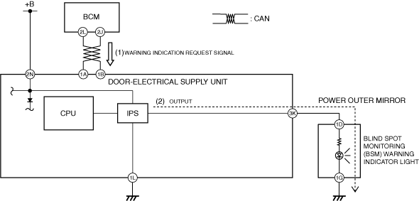
Indicator Light in the power outer mirror
1. The door-electrical supply unit receives (1) the warning indication request signal from the body control module (BCM) using CAN communication.
2. The door-electrical supply unit outputs (2) the blind spot monitoring (BSM) warning indicator light to the power outer mirror based on the warning indication request signal.
3. The power outer mirror turns the blind spot monitoring (BSM) warning indicator light on.
ALARM
Purpose
• The warning alarm alerts the user of the following conditions.
-
― The distance between vehicles is close (MRCC/CTS)
-
• Mazda Radar Cruise Control (MRCC)
• Mazda Radar Cruise Control with Stop & Go function (MRCC with Stop & Go function)
• Cruising & Traffic Alert (CTS)
― The MRCC/CTS system was canceled automatically due to low vehicle speed (MTX)
― Malfunction has occurred in the MRCC/CTS system
― There is the possibility of a collision with a vehicle or obstruction
-
• Smart Brake Support (SBS)
• Smart Brake Support [Rear] (SBS-R)
• Smart Brake Support [Rear Crossing] (SBS-RC)
• Blind Spot Monitoring (BSM)
• Front Cross Traffic Alert (FCTA)
• Rear Cross Traffic Alert (RCTA)
― The vehicle may depart from its lane
-
• Lane Departure Warning System (LDWS)
― Driver’s attention is reduced)
-
• Driver Attention Alert System
• Driver Monitoring (DM)
― The vehicle speed exceeds the speed limit
-
• Adjustable Speed Limiter (ASL)
• Intelligent Speed Assistance (ISA)
Function
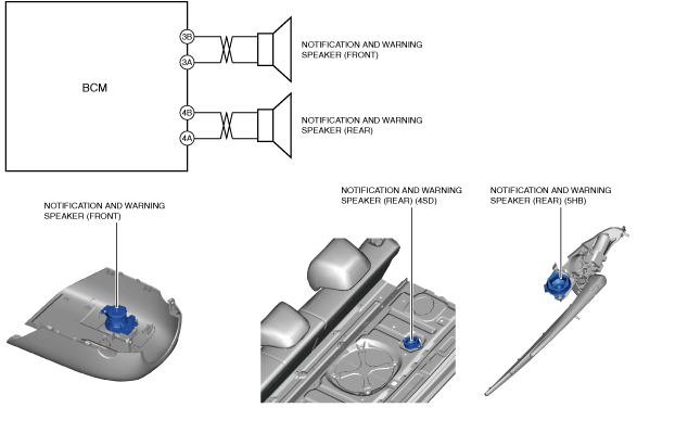
• The body control module (BCM) outputs the warning sound signal to the notification and warning speaker (front).
• The body control module (BCM) outputs the warning sound signal to the nodification and warning speaker (rear).
Construction
• The notification and warning speaker (front) is located on the lower column cover.
• The notification and warning speaker (rear) is located on the rear package tray (4SD)/rear wiper motor bracket(5HB).
Operation
1. The body control module (BCM) outputs warning sound signal to the notification and warning speaker (front/rear).
2. The notification and warning speaker (front/rear) sounds the warning alarm.