|
1
|
DETERMINE IF MALFUNCTION IS STEERING SWITCH
• Switch the ignition ON (engine off or on).
• Display the [Steering SW Inspection] using the diagnostic assist function.
• Among the following switches, are there any that match the operation results display when the steering switch is operated?
-
― Audio system switches (VOL-, VOL+, SEEK-, SEEK+, MUTE)
― Hands-free system switches (SOURCE, PICK-UP/VOICE, HANG-UP)
|
Yes
|
Both audio system switches and hands-free system switches match:
• Verify that the repairs have been completed.
Only audio system switches match:
• Go to Step 7.
Only hands-free system switches match:
• Go to the next step.
|
|
No
|
Go to Step 12.
|
|
2
|
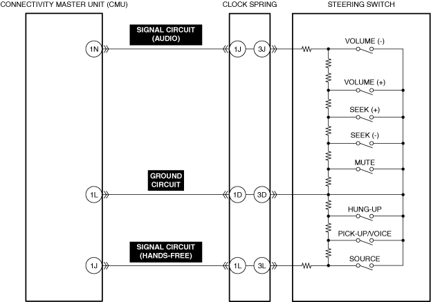
VERIFY CLOCK SPRING (AUDIO SYSTEM) VOLTAGE
• Switch the ignition ON (engine off).
• Measure the voltage at clock spring terminal 3J.
• Is the voltage between 2.68—2.89 V?
|
Yes
|
Go to the next step.
|
|
No
|
Voltage exceeds 2.89 V:
• Go to Step 4.
Voltage is less than 2.68 V:
• Go to Step 5.
|
|
3
|
INSPECT STEERING SWITCH FOR MALFUNCTION
• Inspect the applicable part. (Refer to the [STEERING SWITCH INSPECTION] in the workshop manual)
• Is the part normal?
|
Yes
|
Verify that the repairs have been completed.
|
|
No
|
Repair or replace the malfunctioning location and perform the repair completion verification.
(Refer to the [STEERING SWITCH REMOVAL/INSTALLATION] in the workshop manual)
|
|
4
|
INSPECT STEERING SWITCH SIGNAL CIRCUIT (AUDIO) FOR SHORT TO POWER SUPPLY
• Inspect the applicable circuit for a short to power supply. (Refer to the [CIRCUIT INSPECTION] in the workshop manual)
• Is the circuit normal?
|
Yes
|
Verify that the repairs have been completed.
|
|
No
|
Repair or replace the malfunctioning location and perform the repair completion verification.
|
|
5
|
INSPECT STEERING SWITCH SIGNAL CIRCUIT (AUDIO) FOR SHORT TO GROUND
• Inspect the applicable circuit for a short to ground. (Refer to the [CIRCUIT INSPECTION] in the workshop manual)
• Is the circuit normal?
|
Yes
|
Go to the next step.
|
|
No
|
Repair or replace the malfunctioning location and perform the repair completion verification.
|
|
6
|
INSPECT STEERING SWITCH SIGNAL CIRCUIT (AUDIO) FOR OPEN CIRCUIT
• Inspect the applicable circuit for an open circuit. (Refer to the [CIRCUIT INSPECTION] in the workshop manual)
• Is the circuit normal?
|
Yes
|
Verify that the repairs have been completed.
|
|
No
|
Repair or replace the malfunctioning location and perform the repair completion verification.
|
|
7
|
VERIFY CLOCK SPRING (HANDS-FREE SYSTEM) VOLTAGE
• Switch the ignition ON (engine off).
• Measure the voltage at clock spring terminal 3L.
• Is the voltage between 2.520–2.736 V?
|
Yes
|
Go to the next step.
|
|
No
|
Voltage exceeds 2.736 V:
• Go to Step 9.
Voltage is less than 2.520 V:
• Go to Step 10.
|
|
8
|
INSPECT STEERING SWITCH FOR MALFUNCTION
• Inspect the applicable part. (Refer to the [STEERING SWITCH INSPECTION] in the workshop manual)
• Is the part normal?
|
Yes
|
Verify that the repairs have been completed.
|
|
No
|
Repair or replace the malfunctioning location and perform the repair completion verification.
(Refer to the [STEERING SWITCH REMOVAL/INSTALLATION] in the workshop manual)
|
|
9
|
INSPECT STEERING SWITCH SIGNAL CIRCUIT (HANDS-FREE) FOR SHORT TO POWER SUPPLY
• Inspect the applicable circuit for a short to power supply. (Refer to the [CIRCUIT INSPECTION] in the workshop manual)
• Is the circuit normal?
|
Yes
|
Verify that the repairs have been completed.
|
|
No
|
Repair or replace the malfunctioning location and perform the repair completion verification.
|
|
10
|
INSPECT STEERING SWITCH SIGNAL CIRCUIT (HANDS-FREE) FOR SHORT TO GROUND
• Inspect the applicable circuit for a short to ground. (Refer to the [CIRCUIT INSPECTION] in the workshop manual)
• Is the circuit normal?
|
Yes
|
Go to the next step.
|
|
No
|
Repair or replace the malfunctioning location and perform the repair completion verification.
|
|
11
|
INSPECT STEERING SWITCH SIGNAL CIRCUIT (HANDS-FREE) FOR OPEN CIRCUIT
• Inspect the applicable circuit for an open circuit. (Refer to the [CIRCUIT INSPECTION] in the workshop manual)
• Is the circuit normal?
|
Yes
|
Verify that the repairs have been completed.
|
|
No
|
Repair or replace the malfunctioning location and perform the repair completion verification.
|
|
12
|
VERIFY CLOCK SPRING (AUDIO, HANDS-FREE, AND GROUND SYSTEMS) VOLTAGE
• Switch the ignition ON (engine off).
• Measure the voltage at the following terminals.
-
― Clock spring terminal 3J
― Clock spring terminal 3D
― Clock spring terminal 3L
• Are the voltage values as follows?
-
― Clock spring terminal 3J: 2.68-2.89 V
― Clock spring terminal 3D: 0 V
― Clock spring terminal 3L: 2.520-2.736 V
|
Yes
|
Go to the next step.
|
|
No
|
Go to Step 15.
|
|
13
|
INSPECT CLOCK SPRING (3A—3N TERMINAL) CONNECTOR FOR MALFUNCTION
• Inspect the applicable connector and terminal. (Refer to the [CONNECTOR INSPECTION] in the workshop manual)
• Are the connector and terminal normal?
|
Yes
|
Go to the next step.
|
|
No
|
Repair or replace the malfunctioning location and perform the repair completion verification.
|
|
14
|
INSPECT STEERING SWITCH FOR MALFUNCTION
• Inspect the applicable part. (Refer to the [STEERING SWITCH INSPECTION] in the workshop manual)
• Is the part normal?
|
Yes
|
Verify that the repairs have been completed.
|
|
No
|
Repair or replace the malfunctioning location and perform the repair completion verification.
(Refer to the [STEERING SWITCH REMOVAL/INSTALLATION] in the workshop manual)
|
|
15
|
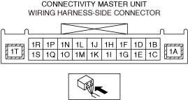
VERIFY CONNECTIVITY MASTER UNIT (CMU) (AUDIO, HANDS-FREE, AND GROUND SYSTEMS) VOLTAGE
• Switch the ignition ON (engine off).
• Measure the voltage at the following terminals.
-
― Connectivity master unit (CMU) terminal 1N
― Connectivity master unit (CMU) terminal 1L
― Connectivity master unit (CMU) terminal 1J
• Are the voltage values as follows?
-
― Connectivity master unit (CMU) terminal 1N: 2.68-2.89 V
― Connectivity master unit (CMU) terminal 1L: 0 V
― Connectivity master unit (CMU) terminal 1J: 2.520-2.736 V
|
Yes
|
Go to the next step.
|
|
No
|
Replace the connectivity master unit (CMU) and perform the repair completion verification.
(Refer to the [CONNECTIVITY MASTER UNIT (CMU) REMOVAL/INSTALLATION] in the workshop manual)
|
|
16
|
INSPECT CONNECTIVITY MASTER UNIT (CMU) CONNECTOR FOR MALFUNCTION
• Inspect the applicable connector and terminal. (Refer to the [CONNECTOR INSPECTION] in the workshop manual)
• Are the connector and terminal normal?
|
Yes
|
Go to the next step.
|
|
No
|
Repair or replace the malfunctioning location and perform the repair completion verification.
|
|
17
|
INSPECT CLOCK SPRING (TERMINAL 1A—1N) CONNECTOR FOR MALFUNCTION
• Inspect the applicable connector and terminal. (Refer to the [CONNECTOR INSPECTION] in the workshop manual)
• Are the connector and terminal normal?
|
Yes
|
Go to the next step.
|
|
No
|
Repair or replace the malfunctioning location and perform the repair completion verification.
|
|
18
|
INSPECT STEERING SWITCH SIGNAL CIRCUIT (AUDIO), SIGNAL CIRCUIT (HANDS-FREE), AND GROUND CIRCUIT FOR SHORT TO POWER SUPPLY
• Inspect the applicable circuit for a short to power supply. (Refer to the [CIRCUIT INSPECTION] in the workshop manual)
• Is the circuit normal?
|
Yes
|
Go to the next step.
|
|
No
|
Repair or replace the malfunctioning location and perform the repair completion verification.
|
|
19
|
INSPECT STEERING SWITCH SIGNAL CIRCUIT (AUDIO), SIGNAL CIRCUIT (HANDS-FREE), AND GROUND CIRCUITS FOR SHORT TO GROUND
• Inspect the applicable circuit for a short to ground. (Refer to the [CIRCUIT INSPECTION] in the workshop manual)
• Is the circuit normal?
|
Yes
|
Go to the next step.
|
|
No
|
Repair or replace the malfunctioning location and perform the repair completion verification.
|
|
20
|
INSPECT STEERING SWITCH SIGNAL CIRCUITS (AUDIO), SIGNAL CIRCUITS (HANDS-FREE), AND GROUND CIRCUITS FOR SHORT CIRCUIT
• Inspect the applicable circuits for a short circuit. (Refer to the [CIRCUIT INSPECTION] in the workshop manual)
• Is the circuit normal?
|
Yes
|
Go to the next step.
|
|
No
|
Repair or replace the malfunctioning location and perform the repair completion verification.
|
|
21
|
INSPECT CLOCK SPRING FOR MALFUNCTION
• Inspect the applicable part. (Refer to the [CLOCK SPRING INSPECTION] in the workshop manual)
• Is the part normal?
|
Yes
|
Go to the next step.
|
|
No
|
Repair or replace the malfunctioning location and perform the repair completion verification.
(Refer to the [CLOCK SPRING REMOVAL/INSTALLATION] in the workshop manual)
|
|
Repair completion verification 1
|
VERIFY THAT VEHICLE IS REPAIRED
• Install/connect the part removed/disconnected during the troubleshooting procedure.
• Clear the DTC recorded in the memory. (Refer to the [CLEARING DTC] in the workshop manual)
• Perform the DTC inspection for the connectivity master unit (CMU). (Refer to the [DTC INSPECTION] in the workshop manual)
• Is the same Pending DTC present?
|
Yes
|
Refer to the controller area network (CAN) malfunction diagnosis flow to inspect for a CAN communication error.
(Refer to the [CONTROLLER AREA NETWORK (CAN) MALFUNCTION DIAGNOSIS FLOW] in the workshop manual)
If the CAN communication is normal, perform the diagnosis from Step 1.
• If the malfunction recurs, replace the connectivity master unit (CMU), then go to the next step. (Refer to the [CONNECTIVITY MASTER UNIT (CMU) REMOVAL/INSTALLATION] in the workshop manual)
|
|
No
|
Go to the next step.
|
|
Repair completion verification 2
|
VERIFY IF OTHER DTCs ARE DISPLAYED
• Perform the DTC inspection. (Refer to the [DTC INSPECTION] in the workshop manual)
• Are other DTCs displayed?
|
Yes
|
Repair the malfunctioning location according to the applicable DTC troubleshooting.
|
|
No
|
DTC troubleshooting completed.
|