|
1
|
VERIFY STEERING SWITCH CONDITION
• Visually inspect each steering switch.
• Are there any switches in the steering switch that are stuck in a pressed condition?
|
Yes
|
Release the stuck switch.
• If foreign matter is caught, remove it if possible.
• The stuck switch and adjacent switch are operated any number of times.
If the stuck switch is released:
• Go to the next step.
If the stuck switch is not released
• Repair or replace the malfunctioning location and perform the repair completion verification. (Refer to the [STEERING SWITCH REMOVAL/INSTALLATION] in the workshop manual)
|
|
No
|
Go to the next step.
|
|
2
|
INSPECT STEERING SWITCH FOR MALFUNCTION
• Inspect the applicable part. (Refer to the [STEERING SWITCH INSPECTION] in the workshop manual)
• Is the part normal?
|
Yes
|
Go to the next step.
|
|
No
|
Repair or replace the malfunctioning location and perform the repair completion verification.
(Refer to the [STEERING SWITCH REMOVAL/INSTALLATION] in the workshop manual)
|
|
3
|
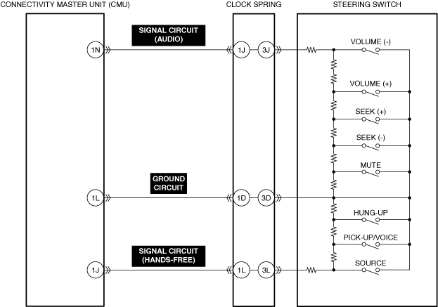
VERIFY CLOCK SPRING (AUDIO, HANDS-FREE, AND GROUND SYSTEMS) VOLTAGE
• Switch the ignition ON (engine off).
• Measure the voltage at the following terminals.
-
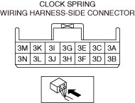
― Clock spring terminal 3J
― Clock spring terminal 3D
― Clock spring terminal 3L
• Are the voltage values as follows?
-
― Clock spring terminal 3J: 2.68-2.89 V
― Clock spring terminal 3D: 0 V
― Clock spring terminal 3L: 2.520-2.736 V
|
Yes
|
Go to the next step.
|
|
No
|
Go to Step 5.
|
|
4
|
INSPECT CLOCK SPRING (TERMINAL 3A—3N) CONNECTOR FOR MALFUNCTION
• Inspect the applicable connector and terminal. (Refer to the [CONNECTOR INSPECTION] in the workshop manual)
• Are the connector and terminal normal?
|
Yes
|
Go to the next step.
|
|
No
|
Repair or replace the malfunctioning location and perform the repair completion verification.
|
|
5
|
VERIFY CONNECTIVITY MASTER UNIT (CMU) (AUDIO, HANDS-FREE, AND GROUND SYSTEMS) VOLTAGE
• Switch the ignition ON (engine off).
• Measure the voltage at the following terminals.
-
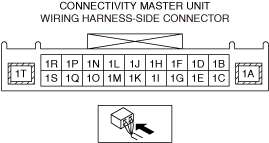
― Connectivity master unit (CMU) terminal 1N
― Connectivity master unit (CMU) terminal 1L
― Connectivity master unit (CMU) terminal 1J
• Are the voltage values as follows?
-
― Connectivity master unit (CMU) terminal 1N: 2.68-2.89 V
― Connectivity master unit (CMU) terminal 1L: 0 V
― Connectivity master unit (CMU) terminal 1J: 2.520-2.736 V
|
Yes
|
Go to the next step.
|
|
No
|
Replace the connectivity master unit (CMU) and perform the repair completion verification.
(Refer to the [CONNECTIVITY MASTER UNIT (CMU) REMOVAL/INSTALLATION] in the workshop manual)
|
|
6
|
INSPECT CONNECTIVITY MASTER UNIT (CMU) CONNECTOR FOR MALFUNCTION
• Inspect the applicable connector and terminal. (Refer to the [CONNECTOR INSPECTION] in the workshop manual)
• Are the connector and terminal normal?
|
Yes
|
Go to the next step.
|
|
No
|
Repair or replace the malfunctioning location and perform the repair completion verification.
|
|
7
|
INSPECT CLOCK SPRING (TERMINAL 1A—1N) CONNECTOR FOR MALFUNCTION
• Inspect the applicable connector and terminal. (Refer to the [CONNECTOR INSPECTION] in the workshop manual)
• Are the connector and terminal normal?
|
Yes
|
Go to the next step.
|
|
No
|
Repair or replace the malfunctioning location and perform the repair completion verification.
|
|
8
|
INSPECT STEERING SWITCH SIGNAL CIRCUIT (AUDIO), SIGNAL CIRCUIT (HANDS-FREE), AND GROUND CIRCUIT FOR SHORT TO POWER SUPPLY
• Inspect the applicable circuit for a short to power supply. (Refer to the [CIRCUIT INSPECTION] in the workshop manual)
• Is the circuit normal?
|
Yes
|
Go to the next step.
|
|
No
|
Repair or replace the malfunctioning location and perform the repair completion verification.
|
|
9
|
INSPECT STEERING SWITCH SIGNAL CIRCUIT (AUDIO), SIGNAL CIRCUIT (HANDS-FREE), AND GROUND CIRCUIT FOR SHORT TO GROUND
• Inspect the applicable circuit for a short to ground. (Refer to the [CIRCUIT INSPECTION] in the workshop manual)
• Is the circuit normal?
|
Yes
|
Go to the next step.
|
|
No
|
Repair or replace the malfunctioning location and perform the repair completion verification.
|
|
10
|
INSPECT STEERING SWITCH SIGNAL CIRCUITS (AUDIO), SIGNAL CIRCUITS (HANDS-FREE), AND GROUND CIRCUITS FOR SHORT CIRCUIT
• Inspect the applicable circuits for a short circuit. (Refer to the [CIRCUIT INSPECTION] in the workshop manual)
• Is the circuit normal?
|
Yes
|
Go to the next step.
|
|
No
|
Repair or replace the malfunctioning location and perform the repair completion verification.
|
|
11
|
INSPECT CLOCK SPRING FOR MALFUNCTION
• Inspect the applicable part. (Refer to the [CLOCK SPRING INSPECTION] in the workshop manual)
• Is the part normal?
|
Yes
|
Go to the next step.
|
|
No
|
Repair or replace the malfunctioning location and perform the repair completion verification.
(Refer to the [CLOCK SPRING REMOVAL/INSTALLATION] in the workshop manual)
|
|
Repair completion verification 1
|
VERIFY THAT VEHICLE IS REPAIRED
• Install/connect the part removed/disconnected during the troubleshooting procedure.
• Clear the DTC recorded in the memory. (Refer to the [CLEARING DTC] in the workshop manual)
• Perform the DTC inspection for the connectivity master unit (CMU). (Refer to the [DTC INSPECTION] in the workshop manual)
• Is the same Pending DTC present?
|
Yes
|
Refer to the controller area network (CAN) malfunction diagnosis flow to inspect for a CAN communication error.
(Refer to the [CONTROLLER AREA NETWORK (CAN) MALFUNCTION DIAGNOSIS FLOW] in the workshop manual)
If the CAN communication is normal, perform the diagnosis from Step 1.
• If the malfunction recurs, replace the connectivity master unit (CMU), then go to the next step. (Refer to the [CONNECTIVITY MASTER UNIT (CMU) REMOVAL/INSTALLATION] in the workshop manual)
|
|
No
|
Go to the next step.
|
|
Repair completion verification 2
|
VERIFY IF OTHER DTCs ARE DISPLAYED
• Perform the DTC inspection. (Refer to the [DTC INSPECTION] in the workshop manual)
• Are other DTCs displayed?
|
Yes
|
Repair the malfunctioning location according to the applicable DTC troubleshooting.
|
|
No
|
DTC troubleshooting completed.
|