|
1
|
INSPECT BODY CONTROL MODULE (BCM), CONNECTIVITY MASTER UNIT (CMU), AND REMOTE TUNER (RT) FOR MALFUNCTION
• Perform the DTC inspection for the body control module (BCM) and the connectivity master unit (CMU). (Refer to the [DTC INSPECTION] in the workshop manual)
• Are any of the following DTCs displayed?
-
― DTC related to malfunction in BCM
― DTC related to malfunction in CMU
― B1A33:49 for CMU
|
Yes
|
Repair the malfunctioning location according to the applicable DTC troubleshooting.
(Refer to the [DTC TABLE [BODY CONTROL MODULE (BCM)]] in the workshop manual)
|
|
No
|
Go to the next step.
|
|
2
|
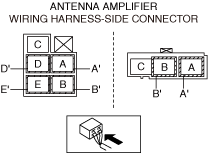
INSPECT ANTENNA AMPLIFIER CONNECTOR FOR MALFUNCTION
• Inspect the applicable connector and terminal. (Refer to the [CONNECTOR INSPECTION] in the workshop manual)
• Are the connector and terminal normal?
|
Yes
|
Go to the next step.
|
|
No
|
Repair or replace the malfunctioning location and perform the repair completion verification.
|
|
3
|
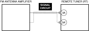
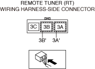
INSPECT REMOTE TUNER (RT) CONNECTOR FOR MALFUNCTION
• Inspect the applicable connector and terminal. (Refer to the [CONNECTOR INSPECTION] in the workshop manual)
• Are the connector and terminal normal?
|
Yes
|
Go to the next step.
|
|
No
|
Repair or replace the malfunctioning location and perform the repair completion verification.
|
|
4
|
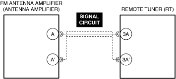
INSPECT FM ANTENNA AMPLIFIER SIGNAL CIRCUIT FOR SHORT TO GROUND
• Inspect the applicable circuit for a short to ground. (Refer to the [CIRCUIT INSPECTION] in the workshop manual)
• Is the circuit normal?
|
Yes
|
Go to the next step.
|
|
No
|
Repair or replace the malfunctioning location and perform the repair completion verification.
|
|
5
|
INSPECT FM ANTENNA AMPLIFIER SIGNAL CIRCUIT FOR SHORT TO POWER SUPPLY
• Inspect the applicable circuit for a short to power supply. (Refer to the [CIRCUIT INSPECTION] in the workshop manual)
• Is the circuit normal?
|
Yes
|
Go to the next step.
|
|
No
|
Repair or replace the malfunctioning location and perform the repair completion verification.
|
|
6
|
INSPECT FM ANTENNA AMPLIFIER SIGNAL CIRCUIT AND MUTUAL SHIELD FOR SHORT CIRCUIT
• Inspect the applicable circuits for a short circuit. (Refer to the [CIRCUIT INSPECTION] in the workshop manual)
• Is the circuit normal?
|
Yes
|
Replace the antenna amplifier and perform the repair completion verification.
(Refer to the [ANTENNA AMPLIFIER REMOVAL/INSTALLATION] in the workshop manual)
|
|
No
|
Repair or replace the malfunctioning location and perform the repair completion verification.
(Refer to the [ANTENNA FEEDER NO.2 REMOVAL/INSTALLATION] in the workshop manual)
|
|
Repair completion verification 1
|
VERIFY THAT VEHICLE IS REPAIRED
• Install/connect the part removed/disconnected during the troubleshooting procedure.
• Clear the DTC recorded in the memory. (Refer to the [CLEARING DTC] in the workshop manual)
• Perform the DTC inspection for the connectivity master unit (CMU). (Refer to the [DTC INSPECTION] in the workshop manual)
• Is the same Pending DTC present?
|
Yes
|
Refer to the controller area network (CAN) malfunction diagnosis flow to inspect for a CAN communication error.
(Refer to the [CONTROLLER AREA NETWORK (CAN) MALFUNCTION DIAGNOSIS FLOW] in the workshop manual)
If the CAN communication is normal, perform the diagnosis from Step 1.
• If the malfunction recurs, replace the remote tuner (RT), then go to the next step. (Refer to the [REMOTE TUNER (RT) REMOVAL/INSTALLATION] in the workshop manual)
|
|
No
|
Go to the next step.
|
|
Repair completion verification 2
|
VERIFY IF OTHER DTCs ARE DISPLAYED
• Perform the DTC inspection. (Refer to the [DTC INSPECTION] in the workshop manual))
• Is a DTC displayed?
|
Yes
|
Repair the malfunctioning location according to the applicable DTC troubleshooting.
|
|
No
|
DTC troubleshooting completed.
|