DTC U0186:08 [CONNECTIVITY MASTER UNIT (E)]


id1602a10079a4


Without Bose®


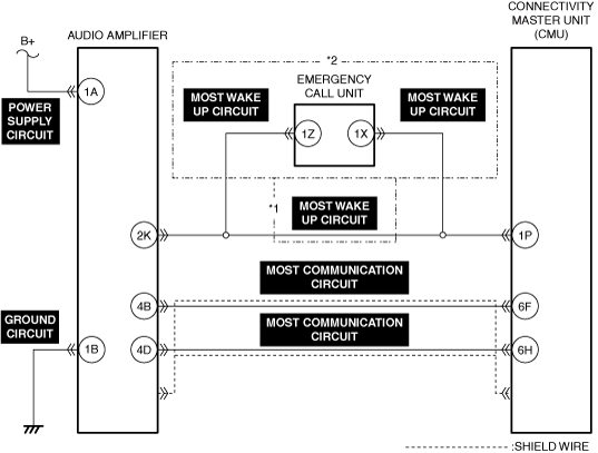
Outline

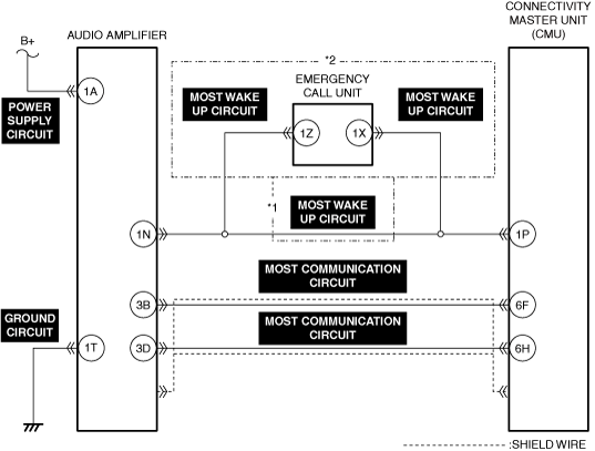
System malfunction location

Communication error with audio amplifier

Detection condition
•  The connectivity master unit (CMU) detects a communication error with the audio amplifier.
Fail-safe
Not applicable
Possible cause
•  Audio amplifier connector or terminal malfunction
•  Emergency call unit connector or terminal malfunction
•  Connectivity master unit (CMU) connector or terminal malfunction
•  Short to ground or open circuit in audio amplifier power supply circuit
•  Open circuit in audio amplifier ground circuit
•  Short to power supply, short to ground or open circuit in MOST WAKE UP circuit
•  Short to power supply, short to ground or open circuit in MOST communication circuit
•  MOST communication circuit shield wire malfunction
•  Audio amplifier malfunction
•  Emergency call unit malfunction
•  Connectivity master unit (CMU) malfunction

*1  :Without Emergency Call System
*2  :With Emergency Call System


Diagnostic Procedure

Step

Inspection

Results

Action

1
VERIFY AUDIO AMPLIFIER OPERATION
•  Output audio in the cabin using the audio amplifier. (Such as radio, navigation)
•  Is audio output from the vehicle speakers?
Yes
Verify that the repairs have been completed.
No
Go to the next step.
2
VERIFY SUPPLY VOLTAGE TO AUDIO AMPLIFIER
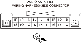
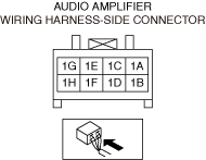
•  Measure the voltage at audio amplifier terminal 1A (vehicle wiring harness side).
•  Is the voltage B+?
Yes
Go to the next step.
No
Repair or replace the malfunctioning location and perform the repair completion verification.
3
INSPECT AUDIO AMPLIFIER GROUND CIRCUIT FOR OPEN CIRCUIT
•  Inspect the audio amplifier ground circuit for open circuit.
(Refer to the [CIRCUIT INSPECTION] in the workshop manual)
•  Is the circuit normal?
Yes
Go to the next step.
No
Repair or replace the malfunctioning location and perform the repair completion verification.
4
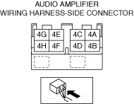
INSPECT AUDIO AMPLIFIER CONNECTOR FOR MALFUNCTION
•  Inspect the applicable connector and terminal.
(Refer to the [CONNECTOR INSPECTION] in the workshop manual)
•  Are the connector and terminal normal?
Yes
Go to the next step.
No
Repair or replace the malfunctioning location and perform the repair completion verification.
5
INSPECT AUDIO AMPLIFIER POWER SUPPLY CIRCUIT FOR SHORT TO GROUND AND OPEN CIRCUIT
•  Inspect the power supply circuit for a short to ground and open circuit.
(Refer to the [CIRCUIT INSPECTION] in the workshop manual)
•  Is the circuit normal?
Yes
Go to the next step.
No
Repair or replace the malfunctioning location and perform the repair completion verification.
6
VERIFY MOST WAKE UP CIRCUIT VOLTAGE
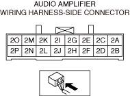
•  Measure the voltage at audio amplifier terminal 1N (vehicle wiring harness side).
•  Is the voltage B+?
Yes
Go to Step 14.
No
Without Emergency Call System:
•  Go to Step 9.
With Emergency Call System:
•  Go to the next step.
7
VERIFY MOST WAKE UP CIRCUIT VOLTAGE
Note
•  Measure while the Emergency Call System is not operating.
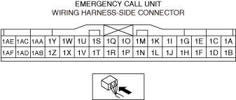
•  Measure the voltage at emergency call unit terminal 1Z.
•  Is the voltage B+?
Yes
Go to the next step.
No
Go to Step 9.
8
INSPECT EMERGENCY CALL UNIT FOR MALFUNCTION
•  Perform the DTC inspection for the emergency call unit.
(Refer to the [DTC INSPECTION] in the workshop manual))
•  Is a DTC displayed?
Yes
Repair the malfunctioning location according to the applicable DTC troubleshooting.
(Refer to the [DTC TABLE [EMERGENCY CALL UNIT]] in the workshop manual)
No
Go to the next step.
9
INSPECT CONNECTIVITY MASTER UNIT (CMU) CONNECTOR FOR MALFUNCTION
•  Inspect the applicable connector and terminal.
(Refer to the [CONNECTOR INSPECTION] in the workshop manual)
•  Are the connector and terminal normal?
Yes
Without Emergency Call System:
•  Go to Step 11.
With Emergency Call System:
•  Go to the next step.
No
Repair or replace the malfunctioning location and perform the repair completion verification.
10
INSPECT EMERGENCY CALL UNIT CONNECTOR FOR MALFUNCTION
•  Inspect the applicable connector and terminal.
(Refer to the [CONNECTOR INSPECTION] in the workshop manual)
•  Are the connector and terminal normal?
Yes
Go to the next step.
No
Repair or replace the malfunctioning location and perform the repair completion verification.
11
INSPECT MOST WAKE UP CIRCUIT FOR SHORT TO GROUND
•  Inspect the applicable circuit for a short to ground.
(Refer to the [CIRCUIT INSPECTION] in the workshop manual)
•  Is the circuit normal?
Yes
Go to the next step.
No
Repair or replace the malfunctioning location and perform the repair completion verification.
12
INSPECT MOST WAKE UP CIRCUIT FOR SHORT TO POWER SUPPLY
•  Inspect the applicable circuit for a short to power supply.
(Refer to the [CIRCUIT INSPECTION] in the workshop manual)
•  Is the circuit normal?
Yes
Go to the next step.
No
Repair or replace the malfunctioning location and perform the repair completion verification.
13
INSPECT MOST WAKE UP CIRCUIT FOR OPEN CIRCUIT
•  Inspect the applicable circuit for an open circuit.
(Refer to the [CIRCUIT INSPECTION] in the workshop manual)
•  Is the circuit normal?
Yes
Go to the next step.
No
Repair or replace the malfunctioning location and perform the repair completion verification.
14
INSPECT AUDIO AMPLIFIER CONNECTOR FOR MALFUNCTION
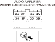
•  Inspect the applicable connector and terminal.
(Refer to the [CONNECTOR INSPECTION] in the workshop manual)
•  Are the connector and terminal normal?
Yes
Go to the next step.
No
Repair or replace the malfunctioning location and perform the repair completion verification.
15
INSPECT CONNECTIVITY MASTER UNIT (CMU) CONNECTOR FOR MALFUNCTION
•  Inspect the applicable connector and terminal.
(Refer to the [CONNECTOR INSPECTION] in the workshop manual)
•  Are the connector and terminal normal?
Yes
Go to the next step.
No
Repair or replace the malfunctioning location and perform the repair completion verification.
16
INSPECT MOST COMMUNICATION CIRCUIT FOR SHORT TO GROUND
•  Inspect the applicable circuit for a short to ground.
(Refer to the [CIRCUIT INSPECTION] in the workshop manual)
•  Is the circuit normal?
Yes
Go to the next step.
No
Repair or replace the malfunctioning location and perform the repair completion verification.
17
INSPECT MOST COMMUNICATION CIRCUIT FOR SHORT TO POWER SUPPLY
•  Inspect the applicable circuit for a short to power supply.
(Refer to the [CIRCUIT INSPECTION] in the workshop manual)
•  Is the circuit normal?
Yes
Go to the next step.
No
Repair or replace the malfunctioning location and perform the repair completion verification.
18
INSPECT MOST COMMUNICATION CIRCUIT FOR OPEN CIRCUIT
•  Inspect the applicable circuit for an open circuit.
(Refer to the [CIRCUIT INSPECTION] in the workshop manual)
•  Is the circuit normal?
Yes
Go to the next step.
No
Repair or replace the malfunctioning location and perform the repair completion verification.
19
INSPECT FOR CONTINUITY BETWEEN MOST COMMUNICATION CIRCUIT SHIELD WIRE AND GROUND
•  Inspect the applicable circuit for continuity with the body ground.
(Refer to the [CIRCUIT INSPECTION] in the workshop manual)
•  Is there continuity?
Yes
Go to the next step.
No
Repair or replace the malfunctioning location and perform the repair completion verification.
20
DETERMINE MALFUNCTIONING LOCATION
•  Replace the audio amplifier.
(Refer to the [AUDIO AMPLIFIER REMOVAL/INSTALLATION] in the workshop manual)
•  Output audio in the cabin using the audio amplifier. (Such as radio, navigation)
•  Is audio output from the vehicle speakers?
Yes
Verify that the repairs have been completed.
No
Put back the audio amplifier that was removed, replace the connectivity master unit (CMU), and perform the repair completion verification.
(Refer to the [AUDIO AMPLIFIER REMOVAL/INSTALLATION] in the workshop manual)
(Refer to the [CONNECTIVITY MASTER UNIT (CMU) REMOVAL/INSTALLATION] in the workshop manual)
Repair completion verification 1
VERIFY THAT VEHICLE IS REPAIRED
•  Install/connect the part removed/disconnected during the troubleshooting procedure.
•  Clear the DTC recorded in the memory.
(Refer to the [CLEARING DTC] in the workshop manual)
•  Perform the DTC inspection for the connectivity master unit (CMU).
(Refer to the [DTC INSPECTION] in the workshop manual)
•  Is the same Pending DTC present?
Yes
Refer to the controller area network (CAN) malfunction diagnosis flow to inspect for a CAN communication error.
(Refer to the [CONTROLLER AREA NETWORK (CAN) MALFUNCTION DIAGNOSIS FLOW] in the workshop manual)
If the CAN communication is normal, perform the diagnosis from Step 1.
•  If the malfunction recurs, replace the connectivity master unit (CMU), then go to the next step.
(Refer to the [CONNECTIVITY MASTER UNIT (CMU) REMOVAL/INSTALLATION] in the workshop manual)
No
Go to the next step.
Repair completion verification 2
VERIFY IF OTHER DTCs ARE DISPLAYED
•  Perform the DTC inspection.
(Refer to the [DTC INSPECTION] in the workshop manual)
•  Are other DTCs displayed?
Yes
Repair the malfunctioning location according to the applicable DTC troubleshooting.
No
DTC troubleshooting completed.


With Bose®


Outline

System malfunction location

Communication error with audio amplifier

Detection condition
•  The connectivity master unit (CMU) detects a communication error with the audio amplifier.
Fail-safe
Not applicable
Possible cause
•  Audio amplifier connector or terminal malfunction
•  Emergency call unit connector or terminal malfunction
•  Connectivity master unit (CMU) connector or terminal malfunction
•  Short to ground or open circuit in audio amplifier power supply circuit
•  Open circuit in audio amplifier ground circuit
•  Short to power supply, short to ground or open circuit in MOST WAKE UP circuit
•  Short to power supply, short to ground or open circuit in MOST communication circuit
•  MOST communication circuit shield wire malfunction
•  Audio amplifier malfunction
•  Emergency call unit malfunction
•  Connectivity master unit (CMU) malfunction

*1  :Without Emergency Call System
*2  :With Emergency Call System


Diagnostic Procedure

Step

Inspection

Results

Action

1
VERIFY AUDIO AMPLIFIER OPERATION
•  Output audio in the cabin using the audio amplifier. (Such as radio, navigation)
•  Is audio output from the vehicle speakers?
Yes
Verify that the repairs have been completed.
No
Go to the next step.
2
VERIFY SUPPLY VOLTAGE TO AUDIO AMPLIFIER
•  Measure the voltage at audio amplifier terminal 1A (vehicle wiring harness side).
•  Is the voltage B+?
Yes
Go to the next step.
No
Repair or replace the malfunctioning location and perform the repair completion verification.
3
INSPECT AUDIO AMPLIFIER GROUND CIRCUIT FOR OPEN CIRCUIT
•  Inspect the audio amplifier ground circuit for open circuit.
(Refer to the [CIRCUIT INSPECTION] in the workshop manual)
•  Is the circuit normal?
Yes
Go to the next step.
No
Repair or replace the malfunctioning location and perform the repair completion verification.
4
INSPECT AUDIO AMPLIFIER CONNECTOR FOR MALFUNCTION
•  Inspect the applicable connector and terminal.
(Refer to the [CONNECTOR INSPECTION] in the workshop manual)
•  Are the connector and terminal normal?
Yes
Go to the next step.
No
Repair or replace the malfunctioning location and perform the repair completion verification.
5
INSPECT AUDIO AMPLIFIER POWER SUPPLY CIRCUIT FOR SHORT TO GROUND AND OPEN CIRCUIT
•  Inspect the power supply circuit for a short to ground and open circuit.
(Refer to the [CIRCUIT INSPECTION] in the workshop manual)
•  Is the circuit normal?
Yes
Go to the next step.
No
Repair or replace the malfunctioning location and perform the repair completion verification.
6
VERIFY MOST WAKE UP CIRCUIT VOLTAGE
•  Measure the voltage at audio amplifier terminal 2K (vehicle wiring harness side).
•  Is the voltage B+?
Yes
Go to Step 14.
No
Without Emergency Call System:
•  Go to Step 9.
With Emergency Call System:
•  Go to the next step.
7
VERIFY MOST WAKE UP CIRCUIT VOLTAGE
Note
•  Measure while the Emergency Call System is not operating.
•  Measure the voltage at emergency call unit terminal 1Z.
•  Is the voltage B+?
Yes
Go to the next step.
No
Go to Step 9.
8
INSPECT EMERGENCY CALL UNIT FOR MALFUNCTION
•  Perform the DTC inspection for the emergency call unit.
(Refer to the [DTC INSPECTION] in the workshop manual))
•  Is a DTC displayed?
Yes
Repair the malfunctioning location according to the applicable DTC troubleshooting.
(Refer to the [DTC TABLE [EMERGENCY CALL UNIT]] in the workshop manual)
No
Go to the next step.
9
INSPECT CONNECTIVITY MASTER UNIT (CMU) CONNECTOR FOR MALFUNCTION
•  Inspect the applicable connector and terminal.
(Refer to the [CONNECTOR INSPECTION] in the workshop manual)
•  Are the connector and terminal normal?
Yes
Without Emergency Call System:
•  Go to Step 11.
With Emergency Call System:
•  Go to the next step.
No
Repair or replace the malfunctioning location and perform the repair completion verification.
10
INSPECT EMERGENCY CALL UNIT CONNECTOR FOR MALFUNCTION
•  Inspect the applicable connector and terminal.
(Refer to the [CONNECTOR INSPECTION] in the workshop manual)
•  Are the connector and terminal normal?
Yes
Go to the next step.
No
Repair or replace the malfunctioning location and perform the repair completion verification.
11
INSPECT MOST WAKE UP CIRCUIT FOR SHORT TO GROUND
•  Inspect the applicable circuit for a short to ground.
(Refer to the [CIRCUIT INSPECTION] in the workshop manual)
•  Is the circuit normal?
Yes
Go to the next step.
No
Repair or replace the malfunctioning location and perform the repair completion verification.
12
INSPECT MOST WAKE UP CIRCUIT FOR SHORT TO POWER SUPPLY
•  Inspect the applicable circuit for a short to power supply.
(Refer to the [CIRCUIT INSPECTION] in the workshop manual)
•  Is the circuit normal?
Yes
Go to the next step.
No
Repair or replace the malfunctioning location and perform the repair completion verification.
13
INSPECT MOST WAKE UP CIRCUIT FOR OPEN CIRCUIT
•  Inspect the applicable circuit for an open circuit.
(Refer to the [CIRCUIT INSPECTION] in the workshop manual)
•  Is the circuit normal?
Yes
Go to the next step.
No
Repair or replace the malfunctioning location and perform the repair completion verification.
14
INSPECT AUDIO AMPLIFIER CONNECTOR FOR MALFUNCTION
•  Inspect the applicable connector and terminal.
(Refer to the [CONNECTOR INSPECTION] in the workshop manual)
•  Are the connector and terminal normal?
Yes
Go to the next step.
No
Repair or replace the malfunctioning location and perform the repair completion verification.
15
INSPECT CONNECTIVITY MASTER UNIT (CMU) CONNECTOR FOR MALFUNCTION
•  Inspect the applicable connector and terminal.
(Refer to the [CONNECTOR INSPECTION] in the workshop manual)
•  Are the connector and terminal normal?
Yes
Go to the next step.
No
Repair or replace the malfunctioning location and perform the repair completion verification.
16
INSPECT MOST COMMUNICATION CIRCUIT FOR SHORT TO GROUND
•  Inspect the applicable circuit for a short to ground.
(Refer to the [CIRCUIT INSPECTION] in the workshop manual)
•  Is the circuit normal?
Yes
Go to the next step.
No
Repair or replace the malfunctioning location and perform the repair completion verification.
17
INSPECT MOST COMMUNICATION CIRCUIT FOR SHORT TO POWER SUPPLY
•  Inspect the applicable circuit for a short to power supply.
(Refer to the [CIRCUIT INSPECTION] in the workshop manual)
•  Is the circuit normal?
Yes
Go to the next step.
No
Repair or replace the malfunctioning location and perform the repair completion verification.
18
INSPECT MOST COMMUNICATION CIRCUIT FOR OPEN CIRCUIT
•  Inspect the applicable circuit for an open circuit.
(Refer to the [CIRCUIT INSPECTION] in the workshop manual)
•  Is the circuit normal?
Yes
Go to the next step.
No
Repair or replace the malfunctioning location and perform the repair completion verification.
19
INSPECT FOR CONTINUITY BETWEEN MOST COMMUNICATION CIRCUIT SHIELD WIRE AND GROUND
•  Inspect the applicable circuit for continuity with the body ground.
(Refer to the [CIRCUIT INSPECTION] in the workshop manual)
•  Is there continuity?
Yes
Go to the next step.
No
Repair or replace the malfunctioning location and perform the repair completion verification.
20
DETERMINE MALFUNCTIONING LOCATION
•  Replace the audio amplifier.
(Refer to the [AUDIO AMPLIFIER REMOVAL/INSTALLATION] in the workshop manual)
•  Output audio in the cabin using the audio amplifier. (Such as radio, navigation)
•  Is audio output from the vehicle speakers?
Yes
Verify that the repairs have been completed.
No
Put back the audio amplifier that was removed, replace the connectivity master unit (CMU), and perform the repair completion verification.
(Refer to the [AUDIO AMPLIFIER REMOVAL/INSTALLATION] in the workshop manual)
(Refer to the [CONNECTIVITY MASTER UNIT (CMU) REMOVAL/INSTALLATION] in the workshop manual)
Repair completion verification 1
VERIFY THAT VEHICLE IS REPAIRED
•  Install/connect the part removed/disconnected during the troubleshooting procedure.
•  Clear the DTC recorded in the memory.
(Refer to the [CLEARING DTC] in the workshop manual)
•  Perform the DTC inspection for the connectivity master unit (CMU).
(Refer to the [DTC INSPECTION] in the workshop manual)
•  Is the same Pending DTC present?
Yes
Refer to the controller area network (CAN) malfunction diagnosis flow to inspect for a CAN communication error.
(Refer to the [CONTROLLER AREA NETWORK (CAN) MALFUNCTION DIAGNOSIS FLOW] in the workshop manual)
If the CAN communication is normal, perform the diagnosis from Step 1.
•  If the malfunction recurs, replace the connectivity master unit (CMU), then go to the next step.
(Refer to the [CONNECTIVITY MASTER UNIT (CMU) REMOVAL/INSTALLATION] in the workshop manual)
No
Go to the next step.
Repair completion verification 2
VERIFY IF OTHER DTCs ARE DISPLAYED
•  Perform the DTC inspection.
(Refer to the [DTC INSPECTION] in the workshop manual)
•  Are other DTCs displayed?
Yes
Repair the malfunctioning location according to the applicable DTC troubleshooting.
No
DTC troubleshooting completed.