|
1
|
VERIFY REPEATABILITY
• Switch the ignition ON (engine off or on).
• Clear the DTC recorded in the memory. (Refer to the [CLEARING DTC] in the workshop manual)
• Switch the ignition OFF, and then switch it ON (engine off or on) and wait for 30 s or more.
• Perform the DTC inspection for the connectivity master unit (CMU). (Refer to the [DTC INSPECTION] in the workshop manual)
• Is the same Pending DTC present?
|
Yes
|
Go to the next step.
|
|
No
|
Go to repair completion verification 2.
|
|
2
|
INSPECT 360°VIEW MONITOR CONTROL MODULE FOR MALFUNCTION
• Perform the DTC inspection for the vehicle control module (VCM) and 360°view monitor control module. (Refer to the [DTC INSPECTION] in the workshop manual)
• Is a DTC displayed?
|
Yes
|
Repair the malfunctioning location according to the applicable DTC troubleshooting.
(Refer to the [DTC TABLE [VEHICLE CONTROL MODULE]] in the workshop manual)
(Refer to the [DTC TABLE [360°VIEW MONITOR CONTROL MODULE]] in the workshop manual)
|
|
No
|
Go to the next step.
|
|
3
|
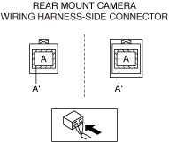
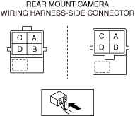
VERIFY REAR MOUNT CAMERA POWER SUPPLY CIRCUIT VOLTAGE
• Measure the voltage at rear mount camera terminal D (vehicle wiring harness side).
• Is voltage supplied?
|
Yes
|
Go to Step 9.
|
|
No
|
Go to the next step.
|
|
4
|
INSPECT REAR MOUNT CAMERA CONNECTOR FOR MALFUNCTION
• Inspect the applicable connector and terminal. (Refer to the [CONNECTOR INSPECTION] in the workshop manual)
• Are the connector and terminal normal?
|
Yes
|
Go to the next step.
|
|
No
|
Repair or replace the malfunctioning location and perform the repair completion verification.
|
|
5
|
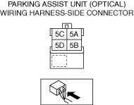
INSPECT 360°VIEW MONITOR CONTROL MODULE CONNECTOR FOR MALFUNCTION
• Inspect the applicable connector and terminal. (Refer to the [CONNECTOR INSPECTION] in the workshop manual)
• Are the connector and terminal normal?
|
Yes
|
Go to the next step.
|
|
No
|
Repair or replace the malfunctioning location and perform the repair completion verification.
|
|
6
|
INSPECT REAR MOUNT CAMERA POWER SUPPLY CIRCUIT FOR SHORT TO GROUND
• Inspect the applicable circuit for a short to ground. (Refer to the [CIRCUIT INSPECTION] in the workshop manual)
• Is the circuit normal?
|
Yes
|
Go to the next step.
|
|
No
|
Repair or replace the malfunctioning location and perform the repair completion verification.
|
|
7
|
INSPECT REAR MOUNT CAMERA POWER SUPPLY CIRCUIT FOR OPEN CIRCUIT
• Inspect the applicable circuit for an open circuit. (Refer to the [CIRCUIT INSPECTION] in the workshop manual)
• Is the circuit normal?
|
Yes
|
Go to the next step.
|
|
No
|
Repair or replace the malfunctioning location and perform the repair completion verification.
|
|
8
|
INSPECT REAR MOUNT CAMERA GROUND CIRCUIT FOR OPEN CIRCUIT
• Inspect the applicable circuit for an open circuit. (Refer to the [CIRCUIT INSPECTION] in the workshop manual)
• Is the circuit normal?
|
Yes
|
Go to Step 11.
|
|
No
|
Repair or replace the malfunctioning location and perform the repair completion verification.
|
|
9
|
INSPECT REAR MOUNT CAMERA CONNECTOR FOR MALFUNCTION
• Inspect the applicable connector and terminal. (Refer to the [CONNECTOR INSPECTION] in the workshop manual)
• Are the connector and terminal normal?
|
Yes
|
Go to the next step.
|
|
No
|
Repair or replace the malfunctioning location and perform the repair completion verification.
|
|
10
|
INSPECT 360°VIEW MONITOR CONTROL MODULE CONNECTOR FOR MALFUNCTION
• Inspect the applicable connector and terminal. (Refer to the [CONNECTOR INSPECTION] in the workshop manual)
• Are the connector and terminal normal?
|
Yes
|
Go to the next step.
|
|
No
|
Repair or replace the malfunctioning location and perform the repair completion verification.
|
|
11
|
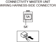
INSPECT CONNECTIVITY MASTER UNIT (CMU) CONNECTOR FOR MALFUNCTION
• Inspect the applicable connector and terminal. (Refer to the [CONNECTOR INSPECTION] in the workshop manual)
• Are the connector and terminal normal?
|
Yes
|
Go to the next step.
|
|
No
|
Repair or replace the malfunctioning location and perform the repair completion verification.
|
|
12
|
INSPECT REAR MOUNT CAMERA SIGNAL CIRCUIT FOR SHORT TO GROUND
• Inspect the applicable circuit for a short to ground. (Refer to the [CIRCUIT INSPECTION] in the workshop manual)
• Is the circuit normal?
|
Yes
|
Go to the next step.
|
|
No
|
Repair or replace the malfunctioning location and perform the repair completion verification.
|
|
13
|
INSPECT REAR MOUNT CAMERA SIGNAL CIRCUIT FOR SHORT TO POWER SUPPLY
• Inspect the applicable circuit for a short to power supply. (Refer to the [CIRCUIT INSPECTION] in the workshop manual)
• Is the circuit normal?
|
Yes
|
Go to the next step.
|
|
No
|
Repair or replace the malfunctioning location and perform the repair completion verification.
|
|
14
|
INSPECT REAR MOUNT CAMERA SIGNAL CIRCUIT FOR OPEN CIRCUIT
• Inspect the applicable circuit for an open circuit. (Refer to the [CIRCUIT INSPECTION] in the workshop manual)
• Is the circuit normal?
|
Yes
|
Go to the next step.
|
|
No
|
Repair or replace the malfunctioning location and perform the repair completion verification.
|
|
15
|
INSPECT FOR CONTINUITY BETWEEN REAR MOUNT CAMERA SIGNAL CIRCUIT SHIELD WIRE AND GROUND
• Inspect the applicable circuit for continuity with the body ground. (Refer to the [CIRCUIT INSPECTION] in the workshop manual)
• Is there continuity?
|
Yes
|
Go to the next step.
|
|
No
|
Repair or replace the malfunctioning location and perform the repair completion verification.
|
|
16
|
INSPECT CONNECTIVITY MASTER UNIT (CMU) SIGNAL CIRCUIT FOR SHORT TO GROUND
• Inspect the applicable circuit for a short to ground. (Refer to the [CIRCUIT INSPECTION] in the workshop manual)
• Is the circuit normal?
|
Yes
|
Go to the next step.
|
|
No
|
Repair or replace the malfunctioning location and perform the repair completion verification.
|
|
17
|
INSPECT CONNECTIVITY MASTER UNIT (CMU) SIGNAL CIRCUIT FOR SHORT TO POWER SUPPLY
• Inspect the applicable circuit for a short to power supply. (Refer to the [CIRCUIT INSPECTION] in the workshop manual)
• Is the circuit normal?
|
Yes
|
Go to the next step.
|
|
No
|
Repair or replace the malfunctioning location and perform the repair completion verification.
|
|
18
|
INSPECT CONNECTIVITY MASTER UNIT (CMU) SIGNAL CIRCUIT FOR OPEN CIRCUIT
• Inspect the applicable circuit for an open circuit. (Refer to the [CIRCUIT INSPECTION] in the workshop manual)
• Is the circuit normal?
|
Yes
|
Go to the next step.
|
|
No
|
Repair or replace the malfunctioning location and perform the repair completion verification.
|
|
19
|
INSPECT FOR CONTINUITY BETWEEN CONNECTIVITY MASTER UNIT (CMU) SIGNAL CIRCUIT AND GROUND
• Inspect the applicable circuit for continuity with the body ground. (Refer to the [CIRCUIT INSPECTION] in the workshop manual)
• Is there continuity?
|
Yes
|
Go to the next step.
|
|
No
|
Repair or replace the malfunctioning location and perform the repair completion verification.
|
|
20
|
DETERMINE MALFUNCTIONING LOCATION
• Clear the DTC recorded in the memory. (Refer to the [CLEARING DTC] in the workshop manual)
• Perform the DTC inspection for the connectivity master unit (CMU). (Refer to the [DTC INSPECTION] in the workshop manual)
• Are other DTCs displayed that are the same as this DTC?
|
Yes
|
Replace the connectivity master unit (CMU) and perform the repair completion verification.
(Refer to the [CONNECTIVITY MASTER UNIT (CMU) REMOVAL/INSTALLATION] in the workshop manual)
|
|
No
|
Replace the rear mount camera and perform the repair completion verification.
(Refer to the [REAR MOUNT CAMERA REMOVAL/INSTALLATION] in the workshop manual)
|
|
Repair completion verification 1
|
VERIFY THAT VEHICLE IS REPAIRED
• Install/connect the part removed/disconnected during the troubleshooting procedure.
• Clear the DTC recorded in the memory. (Refer to the [CLEARING DTC] in the workshop manual)
• Perform the DTC inspection for the connectivity master unit (CMU). (Refer to the [DTC INSPECTION] in the workshop manual)
• Is the same Pending DTC present?
|
Yes
|
Refer to the controller area network (CAN) malfunction diagnosis flow to inspect for a CAN communication error.
(Refer to the [CONTROLLER AREA NETWORK (CAN) MALFUNCTION DIAGNOSIS FLOW] in the workshop manual)
If the CAN communication is normal, perform the diagnosis from Step 1.
• If the malfunction recurs, replace the connectivity master unit (CMU), then go to the next step. (Refer to the [CONNECTIVITY MASTER UNIT (CMU) REMOVAL/INSTALLATION] in the workshop manual)
|
|
No
|
Go to the next step.
|
|
Repair completion verification 2
|
VERIFY IF OTHER DTCs ARE DISPLAYED
• Perform the DTC inspection. (Refer to the [DTC INSPECTION] in the workshop manual)
• Are other DTCs displayed?
|
Yes
|
Repair the malfunctioning location according to the applicable DTC troubleshooting.
|
|
No
|
DTC troubleshooting completed.
|