|
1
|
VERIFY REPEATABILITY
• Switch the ignition ON (engine off or on).
• Clear the DTC recorded in the memory. (Refer to the [CLEARING DTC] in the workshop manual)
• Switch the ignition OFF, and then switch it ON (engine off or on) and wait for 30 s or more.
• Perform the DTC inspection for the connectivity master unit (CMU). (Refer to the [DTC INSPECTION] in the workshop manual)
• Is the same Pending DTC present?
|
Yes
|
Perform the DTC inspection for the emergency call unit.
(Refer to the [DTC INSPECTION] in the workshop manual)
If DTC is displayed
• Repair the malfunctioning location according to the applicable DTC troubleshooting. (Refer to the [DTC TABLE [EMERGENCY CALL UNIT]] in the workshop manual)
If DTC is not displayed
• Go to the next step.
|
|
No
|
Go to repair completion verification 2.
|
|
2
|
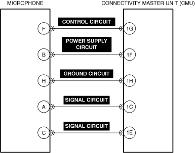
VERIFY VOLTAGE SUPPLIED TO MICROPHONE
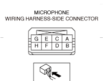
• Measure the voltage at microphone terminal B (vehicle wiring harness side).
• Is the voltage approx. 8.0 V?
|
Yes
|
Go to Step 9.
|
|
No
|
Go to the next step.
|
|
3
|
VERIFY VOLTAGE WHICH EMERGENCY CALL UNIT IS SUPPLYING
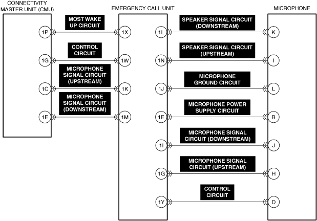
• Measure the voltage at emergency call unit 1E.
• Is the voltage approx. 8.0 V?
|
Yes
|
Go to the next step.
|
|
No
|
Replace the emergency call unit and perform the repair completion verification.
(Refer to the [EMERGENCY CALL UNIT REMOVAL/INSTALLATION] in the workshop manual)
|
|
4
|
INSPECT MICROPHONE CONNECTOR FOR MALFUNCTION
• Inspect the applicable connector and terminal. (Refer to the [CONNECTOR INSPECTION] in the workshop manual)
• Are the connector and terminal normal?
|
Yes
|
Go to the next step.
|
|
No
|
Repair or replace the malfunctioning location and perform the repair completion verification.
|
|
5
|
INSPECT EMERGENCY CALL UNIT CONNECTOR FOR MALFUNCTION
• Inspect the applicable connector and terminal. (Refer to the [CONNECTOR INSPECTION] in the workshop manual)
• Are the connector and terminal normal?
|
Yes
|
Go to the next step.
|
|
No
|
Repair or replace the malfunctioning location and perform the repair completion verification.
|
|
6
|
INSPECT MICROPHONE POWER SUPPLY CIRCUIT FOR SHORT TO GROUND
• Inspect the applicable circuit for a short to ground. (Refer to the [CIRCUIT INSPECTION] in the workshop manual)
• Is the circuit normal?
|
Yes
|
Go to the next step.
|
|
No
|
Repair or replace the malfunctioning location and perform the repair completion verification.
|
|
7
|
INSPECT MICROPHONE POWER SUPPLY CIRCUIT FOR SHORT TO POWER SUPPLY
• Inspect the applicable circuit for a short to power supply. (Refer to the [CIRCUIT INSPECTION] in the workshop manual)
• Is the circuit normal?
|
Yes
|
Go to the next step.
|
|
No
|
Repair or replace the malfunctioning location and perform the repair completion verification.
|
|
8
|
INSPECT MICROPHONE POWER SUPPLY CIRCUIT FOR OPEN CIRCUIT
• Inspect the applicable circuit for an open circuit. (Refer to the [CIRCUIT INSPECTION] in the workshop manual)
• Is the circuit normal?
|
Yes
|
Go to the next step.
|
|
No
|
Repair or replace the malfunctioning location and perform the repair completion verification.
|
|
9
|
INSPECT MICROPHONE CONNECTOR FOR MALFUNCTION
• Inspect the applicable connector and terminal. (Refer to the [CONNECTOR INSPECTION] in the workshop manual)
• Are the connector and terminal normal?
|
Yes
|
Go to the next step.
|
|
No
|
Repair or replace the malfunctioning location and perform the repair completion verification.
|
|
10
|
INSPECT EMERGENCY CALL UNIT CONNECTOR FOR MALFUNCTION
• Inspect the applicable connector and terminal. (Refer to the [CONNECTOR INSPECTION] in the workshop manual)
• Are the connector and terminal normal?
|
Yes
|
Go to the next step.
|
|
No
|
Repair or replace the malfunctioning location and perform the repair completion verification.
|
|
11
|
INSPECT MICROPHONE GROUND CIRCUIT FOR OPEN CIRCUIT
• Inspect the applicable circuit for an open circuit. (Refer to the [CIRCUIT INSPECTION] in the workshop manual)
• Is the circuit normal?
|
Yes
|
Go to the next step.
|
|
No
|
Repair or replace the malfunctioning location and perform the repair completion verification.
|
|
12
|
VERIFY VOLTAGE SUPPLIED FROM MICROPHONE CONTROL CIRCUIT
• Measure the voltage at microphone terminal D (vehicle wiring harness side).
• Is the voltage approx. 8.0 V?
|
Yes
|
Replace the microphone and perform the repair completion verification
(Refer to the [MICROPHONE REMOVAL/INSTALLATION] in the workshop manual)
|
|
No
|
Go to the next step.
|
|
13
|
VERIFY VOLTAGE SUPPLIED AT CONTROL CIRCUIT CONTROLLED BY EMERGENCY CALL UNIT
• Measure the voltage at emergency call unit terminal 1Y.
• Is the voltage approx. 8.0 V?
|
Yes
|
Go to the next step.
|
|
No
|
Replace the emergency call unit and perform the repair completion verification.
(Refer to the [EMERGENCY CALL UNIT REMOVAL/INSTALLATION] in the workshop manual)
|
|
14
|
INSPECT MICROPHONE CONTROL CIRCUIT FOR SHORT TO GROUND
• Inspect the applicable circuit for a short to ground. (Refer to the [CIRCUIT INSPECTION] in the workshop manual)
• Is the circuit normal?
|
Yes
|
Go to the next step.
|
|
No
|
Repair or replace the malfunctioning location and perform the repair completion verification.
|
|
15
|
INSPECT MICROPHONE CONTROL CIRCUIT FOR SHORT TO POWER SUPPLY
• Inspect the applicable circuit for a short to power supply. (Refer to the [CIRCUIT INSPECTION] in the workshop manual)
• Is the circuit normal?
|
Yes
|
Go to the next step.
|
|
No
|
Repair or replace the malfunctioning location and perform the repair completion verification.
|
|
16
|
INSPECT MICROPHONE CONTROL CIRCUIT FOR OPEN CIRCUIT
• Inspect the applicable circuit for an open circuit. (Refer to the [CIRCUIT INSPECTION] in the workshop manual)
• Is the circuit normal?
|
Yes
|
Go to the next step.
|
|
No
|
Repair or replace the malfunctioning location and perform the repair completion verification.
|
|
17
|
VERIFY VOLTAGE SUPPLIED FROM EMERGENCY CALL UNIT CONTROL CIRCUIT
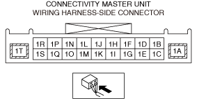
• Measure the voltage at emergency call unit terminal 1W (vehicle wiring harness side).
• Is the voltage approx. 5.43 V?
|
Yes
|
Replace the emergency call unit and perform the repair completion verification.
(Refer to the [EMERGENCY CALL UNIT REMOVAL/INSTALLATION] in the workshop manual)
|
|
No
|
Go to the next step.
|
|
18
|
VERIFY VOLTAGE SUPPLIED AT CONTROL CIRCUIT CONTROLLED BY CONNECTIVITY MASTER UNIT (CMU)
• Measure the voltage at connectivity master unit (CMU) terminal 1G.
• Is the voltage approx. 5.43 V?
|
Yes
|
Go to the next step.
|
|
No
|
Replace the connectivity master unit (CMU) and perform the repair completion verification.
(Refer to the [CONNECTIVITY MASTER UNIT (CMU) REMOVAL/INSTALLATION] in the workshop manual)
|
|
19
|
INSPECT CONNECTIVITY MASTER UNIT (CMU) CONNECTOR FOR MALFUNCTION
• Inspect the applicable connector and terminal. (Refer to the [CONNECTOR INSPECTION] in the workshop manual)
• Are the connector and terminal normal?
|
Yes
|
Go to the next step.
|
|
No
|
Repair or replace the malfunctioning location and perform the repair completion verification.
|
|
20
|
INSPECT EMERGENCY CALL UNIT CONTROL CIRCUIT FOR SHORT TO GROUND
• Inspect the applicable circuit for a short to ground. (Refer to the [CIRCUIT INSPECTION] in the workshop manual)
• Is the circuit normal?
|
Yes
|
Go to the next step.
|
|
No
|
Repair or replace the malfunctioning location and perform the repair completion verification.
|
|
21
|
INSPECT EMERGENCY CALL UNIT CONTROL CIRCUIT FOR SHORT TO POWER SUPPLY
• Inspect the applicable circuit for a short to power supply. (Refer to the [CIRCUIT INSPECTION] in the workshop manual)
• Is the circuit normal?
|
Yes
|
Go to the next step.
|
|
No
|
Repair or replace the malfunctioning location and perform the repair completion verification.
|
|
22
|
INSPECT EMERGENCY CALL UNIT CONTROL CIRCUIT FOR OPEN CIRCUIT
• Inspect the applicable circuit for an open circuit. (Refer to the [CIRCUIT INSPECTION] in the workshop manual)
• Is the circuit normal?
|
Yes
|
Replace the emergency call unit and perform the repair completion verification.
(Refer to the [EMERGENCY CALL UNIT REMOVAL/INSTALLATION] in the workshop manual)
|
|
No
|
Repair or replace the malfunctioning location and perform the repair completion verification.
|
|
Repair completion verification 1
|
VERIFY THAT VEHICLE IS REPAIRED
• Install/connect the part removed/disconnected during the troubleshooting procedure.
• Clear the DTC recorded in the memory. (Refer to the [CLEARING DTC] in the workshop manual)
• Perform the DTC inspection for the connectivity master unit (CMU). (Refer to the [DTC INSPECTION] in the workshop manual)
• Is the same Pending DTC present?
|
Yes
|
Refer to the controller area network (CAN) malfunction diagnosis flow to inspect for a CAN communication error.
(Refer to the [CONTROLLER AREA NETWORK (CAN) MALFUNCTION DIAGNOSIS FLOW] in the workshop manual)
If the CAN communication is normal, perform the diagnosis from Step 1.
• If the malfunction recurs, replace the connectivity master unit (CMU), then go to the next step. (Refer to the [CONNECTIVITY MASTER UNIT (CMU) REMOVAL/INSTALLATION] in the workshop manual)
|
|
No
|
Go to the next step.
|
|
Repair completion verification 2
|
VERIFY IF OTHER DTCs ARE DISPLAYED
• Perform the DTC inspection. (Refer to the [DTC INSPECTION] in the workshop manual)
• Are other DTCs displayed?
|
Yes
|
Repair the malfunctioning location according to the applicable DTC troubleshooting.
|
|
No
|
DTC troubleshooting completed.
|