|
1
|
VISUALLY INSPECT SD CARD
• Visually inspect the SD card for looseness or damage.
• Verify that there is no problem with the SD card using a PC.
• Is the SD card normal?
|
Yes
|
Go to the next step.
|
|
No
|
Repair or replace the malfunctioning location and perform the repair completion verification.
|
|
2
|
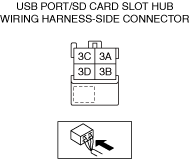
INSPECT USB PORT/SD CARD SLOT HUB CONNECTOR FOR MALFUNCTION
• Inspect the applicable connector and terminal. (Refer to the [CONNECTOR INSPECTION] in the workshop manual)
• Are the connector and terminal normal?
|
Yes
|
Go to the next step.
|
|
No
|
Repair or replace the malfunctioning location and perform the repair completion verification.
|
|
3
|
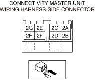
INSPECT CONNECTIVITY MASTER UNIT (CMU) CONNECTOR FOR MALFUNCTION
• Inspect the applicable connector and terminal. (Refer to the [CONNECTOR INSPECTION] in the workshop manual)
• Are the connector and terminal normal?
|
Yes
|
Go to the next step.
|
|
No
|
Repair or replace the malfunctioning location and perform the repair completion verification.
|
|
4
|
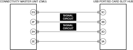
INSPECT USB PORT/SD CARD SLOT HUB CIRCUIT FOR SHORT TO POWER SUPPLY
• Inspect the applicable circuit for a short to power supply. (Refer to the [CIRCUIT INSPECTION] in the workshop manual)
• Is the circuit normal?
|
Yes
|
Go to the next step.
|
|
No
|
Repair or replace the malfunctioning location and perform the repair completion verification.
|
|
5
|
INSPECT USB PORT/SD CARD SLOT HUB CIRCUIT FOR SHORT TO GROUND
• Inspect the applicable circuit for a short to ground. (Refer to the [CIRCUIT INSPECTION] in the workshop manual)
• Is the circuit normal?
|
Yes
|
Go to the next step.
|
|
No
|
Repair or replace the malfunctioning location and perform the repair completion verification.
|
|
6
|
INSPECT USB PORT/SD CARD SLOT HUB CIRCUIT FOR OPEN CIRCUIT
• Inspect the applicable circuit for an open circuit. (Refer to the [CIRCUIT INSPECTION] in the workshop manual)
• Is the circuit normal?
|
Yes
|
Go to the next step.
|
|
No
|
Repair or replace the malfunctioning location and perform the repair completion verification.
|
|
7
|
INSPECT USB PORT/SD CARD SLOT HUB FOR MALFUNCTION DEPENDING ON REPEATABILITY
• Clear the DTC recorded in the memory. (Refer to the [CLEARING DTC] in the workshop manual)
• Switch the ignition ON (engine off or on) and wait for 31 s or more.
• Perform the DTC inspection for the connectivity master unit (CMU). (Refer to the [DTC INSPECTION] in the workshop manual)
• Is the same Pending DTC present?
|
Yes
|
Refer to the controller area network (CAN) malfunction diagnosis flow to inspect for a CAN communication error.
(Refer to the [CONTROLLER AREA NETWORK (CAN) MALFUNCTION DIAGNOSIS FLOW] in the workshop manual)
If the CAN communication is normal, replace the USB port/SD card slot hub and perform the repair completion verification.
(Refer to the [USB PORT/SD CARD SLOT HUB REMOVAL/INSTALLATION] in the workshop manual)
|
|
No
|
Go to repair completion verification.
|
|
8
|
VERIFY IF SD CARD IS VALID
• Perform diagnostic assist function “Storage Diagnostic Test” MAP Areas. (Refer to the [DIAGNOSTIC ASSISTFUNCTION] in the workshop manual)
• Is the SD card normal?
|
Yes
|
Go to the next step.
|
|
No
|
Repair or replace the malfunctioning location and perform the repair completion verification.
|
|
Repair completion verification 1
|
VERIFY THAT VEHICLE IS REPAIRED
• Install/connect the part removed/disconnected during the troubleshooting procedure.
• Clear the DTC recorded in the memory. (Refer to the [CLEARING DTC] in the workshop manual)
• Switch the ignition ON (engine off or on) and wait for 31 s or more.
• Perform the DTC inspection for the connectivity master unit (CMU). (Refer to the [DTC INSPECTION] in the workshop manual)
• Is the same Pending DTC present?
|
Yes
|
Refer to the controller area network (CAN) malfunction diagnosis flow to inspect for a CAN communication error.
(Refer to the [CONTROLLER AREA NETWORK (CAN) MALFUNCTION DIAGNOSIS FLOW] in the workshop manual)
If the CAN communication is normal, perform the diagnosis from Step 1.
• If the malfunction recurs, replace the connectivity master unit (CMU), then go to the next step. (Refer to the [CONNECTIVITY MASTER UNIT (CMU) REMOVAL/INSTALLATION] in the workshop manual)
|
|
No
|
Go to the next step.
|
|
Repair completion verification 2
|
VERIFY IF OTHER DTCs ARE DISPLAYED
• Perform the DTC inspection. (Refer to the [DTC INSPECTION] in the workshop manual)
• Is a DTC displayed?
|
Yes
|
Repair the malfunctioning location according to the applicable DTC troubleshooting.
|
|
No
|
DTC troubleshooting completed.
|