|
1
|
VERIFY FREEZE FRAME DATA (MODE2) OR SNAPSHOT DATA HAVE BEEN RECORDED
• Have FREEZE FRAME DATA (mode2) or snapshot data been recorded?
|
Yes
|
Go to the next step.
|
|
No
|
Record the FREEZE FRAME DATA (mode2) and snapshot data on the repair order, then go to the next step.
|
|
2
|
VERIFY RELATED SERVICE INFORMATION AVAILABILITY
• Verify related Service Information availability.
• Is any related Service Information available?
|
Yes
|
Perform the repair or diagnosis according to the available Service Information.
• If the vehicle is not repaired, go to the next step.
|
|
No
|
Go to the next step.
|
|
3
|
VERIFY CURRENT SIGNAL STATUS: IS CONCERN INTERMITTENT OR CONSTANT?
• Connect the M-MDS to the DLC-2.
• Clear the DTC from the PCM memory using the M-MDS.
• Start the engine.
• Is the PENDING CODE for this DTC present?
|
Yes
|
Go to the next step.
|
|
No
|
Intermittent concern exists.
Perform the “INTERMITTENT CONCERN TROUBLESHOOTING”.
|
|
4
|
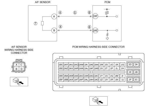
INSPECT A/F SENSOR CONNECTOR FOR POOR CONNECTION
• Switch the ignition to off.
• Disconnect the A/F sensor connector.
• Inspect for poor connection (such as damaged/pulled-out pins, corrosion).
• Is there any malfunction?
|
Yes
|
Repair or replace the terminal, then go to Step 8.
|
|
No
|
Go to the next step.
|
|
5
|
INSPECT A/F SENSOR SIGNAL CIRCUIT FOR SHORT TO GROUND
• Switch the ignition to off.
• Disconnect the A/F sensor connector.
• Inspect for continuity between A/F sensor terminal A (wiring harness-side) and body ground.
• Is there continuity?
|
Yes
|
Repair or replace the wiring harness for a possible short to ground.
If the short to ground circuit could not be detected in wiring harness, replace the PCM (PCM internal circuit short to ground).
Then go to Step 8.
|
|
No
|
Go to the next step.
|
|
6
|
INSPECT PCM CONNECTOR FOR POOR CONNECTION
• Switch the ignition to off.
• Disconnect the PCM connector.
• Inspect for poor connection (such as damaged/pulled-out pins, corrosion).
• Is there any malfunction?
|
Yes
|
Repair or replace the terminal, then go to Step 8.
|
|
No
|
Go to the next step.
|
|
7
|
INSPECT A/F SENSOR
• Inspect the A/F sensor.
• Is there any malfunction?
|
Yes
|
Replace the A/F sensor, then go to the next step.
|
|
No
|
Go to the next step.
|
|
8
|
VERIFY TROUBLESHOOTING OF DTC P0131:00 COMPLETED
• Make sure to reconnect all disconnected connectors.
• Clear the DTC from the PCM memory using the M-MDS.
• Start the engine.
• Is the PENDING CODE for this DTC present?
|
Yes
|
Replace the PCM, then go to the next step.
|
|
No
|
Go to the next step.
|
|
9
|
VERIFY AFTER REPAIR PROCEDURE
• Perform the “AFTER REPAIR PROCEDURE”.
• Are any DTCs present?
|
Yes
|
Go to the applicable DTC inspection.
|
|
No
|
DTC troubleshooting completed.
|