 |
am3zzw00005280
ON-BOARD DIAGNOSTIC TEST [MZR-CD 2.2]
id0102f3801000
DTC Reading Procedure
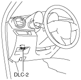
1. Connect the M-MDS to the DLC‐2.
am3zzw00005280
|
2. After the vehicle is identified, select the following items from the initialization screen of the M-MDS.
3. Then, select the “Retrieve CMDTCs” and perform procedures according to directions on the M-MDS screen.
4. Verify the DTC according to the directions on the M-MDS screen.
5. After completion of repairs, clear all DTCs stored in the PCM, while referring to “AFTER REPAIR PROCEDURE“.
Pending Trouble Code Access Procedure
1. Connect the M-MDS to the DLC‐2.
am3zzw00005280
|
2. After the vehicle is identified, select the following items from the initialization screen of the M-MDS.
3. Then, select the “Retrieve CMDTCs” and perform procedures according to directions on the M-MDS screen.
4. Retrieve the pending trouble codes according to the directions on the M-MDS screen.
Freeze Frame PID Data Access Procedure
1. Connect the M-MDS to the DLC‐2.
am3zzw00005280
|
2. After the vehicle is identified, select the following items from the initialization screen of the M-MDS.
3. Then, select the “Retrieve CMDTCs” and perform procedures according to directions on the M-MDS screen.
4. Retrieve the freeze frame PID data according to the directions on the M-MDS screen.
Freeze frame data table
|
Freeze frame data item |
Unit |
Description |
Corresponding PID data monitor item |
|---|---|---|---|
|
LOAD
|
%
|
Ratio of current intake air amount to wide open throttle engine operation intake air amount
|
LOAD
|
|
ECT
|
°C
|
Engine coolant temperature
|
ECT
|
|
MAP
|
Kpa
|
Manifold absolute pressure
|
MAP
|
|
RPM
|
RPM
|
Engine speed
|
RPM
|
|
VSS
|
KPH
|
Vehicle speed input from ABS/DSC HU/CM
|
VSS
|
|
BAT
|
°C
|
Intake air temperature after super charged
|
BAT
|
|
MAF
|
g/Sec
|
Mass airflow of intake-air
|
MAF
|
|
TP
|
%
|
Intake shutter valve position
|
ISV_POS
|
|
FRP
|
Kpa
|
Fuel pressure at common rail
|
FRP
|
|
EQ_RAT11
|
—
|
Ratio of consumed air amount based on engine operation and theoretical air amount
|
—
|
|
O2S11
|
V
|
A/F sensor output voltage
|
—
|
|
WARMUPS
|
—
|
Number of warm-up cycles after all stored DTCs cleared
|
—
|
|
CLR_DIST
|
km
|
Mileage after all stored DTCs cleared
|
—
|
|
BARO
|
Kpa
|
Barometric pressure
|
BARO
|
|
EQ_RAT11
|
—
|
Ratio of consumed air amount based on engine operation and theoretical air amount
|
EQ_RAT11
|
|
O2S11
|
A
|
A/F sensor output current
|
O2S11
|
|
CATTEMP11
|
°C
|
Exhaust gas temperature sensor No.1 value
|
EXHTEMP1
|
|
CATTEMP21
|
°C
|
Exhaust gas temperature sensor No.2 value
|
EXHTEMP2
|
|
VPWR
|
V
|
PCM power supply voltage
|
VPWR
|
|
AAT
|
°C
|
Intake air temperature
|
IAT
|
|
APP_D
|
%
|
APP sensor No.1 value
|
APP1
|
|
APP_E
|
%
|
APP sensor No.2 value
|
APP2
|
|
TAC_PCT
|
%
|
Target intake shutter valve opening angle calculated from engine operating conditions
|
ISV_DSD
|
Snapshot data table
|
Snapshot data item |
Unit |
Description |
Corresponding PID data monitor item |
|---|---|---|---|
|
LOAD
|
%
|
Ratio of current intake air amount to wide open throttle engine operation intake air amount
|
LOAD
|
|
ECT
|
°C
|
Engine coolant temperature
|
ECT
|
|
MAP
|
Pa
|
Manifold absolute pressure
|
MAP
|
|
RPM
|
RPM
|
Engine speed
|
RPM
|
|
VSS
|
KPH
|
Vehicle speed input from ABS/DSC HU/CM
|
VSS
|
|
BAT
|
°C
|
Intake air temperature after super charged
|
BAT
|
|
MAF
|
g/sec
|
Mass airflow of intake-air
|
MAF
|
|
ISV_POS
|
%
|
Intake shutter valve position
|
ISV_POS
|
|
FRP
|
Pa
|
Fuel pressure at common rail
|
FRP
|
|
O2S11
|
V
|
A/F sensor output voltage
|
—
|
|
A
|
A/F sensor output current
|
O2S11
|
|
|
CLR_CNT
|
—
|
Number of warm-up cycles after all stored DTCs cleared
|
—
|
|
CLR_DIST
|
Km
|
Mileage after all stored DTCs cleared
|
—
|
|
BARO
|
Pa
|
Barometric pressure
|
BARO
|
|
EQ_RAT11
|
—
|
Ratio of consumed air amount based on engine operation and theoretical air amount
|
EQ_RAT11
|
|
EXHTEMP1
|
°C
|
Exhaust gas temperature sensor No.1 value
|
EXHTEMP1
|
|
EXHTEMP2
|
°C
|
Exhaust gas temperature sensor No.2 value
|
EXHTEMP2
|
|
EXHTEMP3
|
°C
|
Exhaust gas temperature sensor No.3 value
|
EXHTEMP3
|
|
VPWR
|
V
|
PCM power supply voltage
|
VPWR
|
|
IAT
|
°C
|
Intake air temperature
|
IAT
|
|
APP1
|
%
|
APP sensor No.1 value
|
APP1
|
|
APP2
|
%
|
APP sensor No.2 value
|
APP2
|
|
ISV_DSD
|
%
|
Target intake shutter valve opening angle calculated from engine operating conditions
|
ISV_DSD
|
PID/DATA Monitor And Record Procedure
1. Connect the M-MDS to the DLC‐2.
am3zzw00005280
|
2. After the vehicle is identified, select the following items from the initialization screen of the M-MDS.
3. Select the PID from the PID table.
4. Verify the PID data according to the directions on the M-MDS screen.
Active Command Modes Procedure
1. Connect the M-MDS to the DLC‐2.
am3zzw00005280
|
2. After the vehicle is identified, select the following items from the initialization screen of the M-MDS.
3. Select the simulation items from the PID table.
4. Perform the simulation function, inspect the operations for each parts.