 |
am3zzn00003180
ON-BOARD DIAGNOSTIC SYSTEM TEST MODE [MZ-CD 1.6 (Y6) (EURO4 emission level)]
id0102g6100200
|
Diagnostic test mode |
Item |
|---|---|
|
Mode 01
|
Sending diagnostic data (PID data monitor/On-board system readiness test)
|
|
Mode 02
|
Sending freeze frame data
|
|
Mode 03
|
Sending emission-related malfunction code (DTC)
|
|
Mode 04
|
Clearing/resetting emission-related malfunction information
|
|
Mode 06
|
Sending intermittent monitoring system test results (DMTR)
|
|
Mode 07
|
Sending continuous monitoring system test results (pending code)
|
|
Mode 09
|
Request vehicle information
|
Sending Freeze Frame Data
Freeze frame data table (mode2, mode12) table
|
Freeze frame data item |
Unit |
Description |
Corresponding PID data monitor item |
|---|---|---|---|
|
LOAD
|
%
|
Calculated engine load
|
LOAD
|
|
ECT
|
°C
|
Engine coolant temperature
|
ECT
|
|
MAP
|
kPa
|
Manifold absolute pressure
|
MAP
|
|
RPM
|
RPM
|
Engine speed
|
RPM
|
|
VS
|
KPH
|
Vehicle speed
|
VSS
|
|
IAT
|
°C
|
Intake air temperature
|
IAT
|
|
MAF
|
g/sec
|
Mass airflow
|
MAF
|
|
FRP
|
kPa
|
Fuel pressure
|
FRP
|
|
APP_D
|
%
|
Accelerator pedal position No.1
|
APP1
|
Sending Emission-related Malfunction Code
DTC table (PCM)
|
DTC |
DTC Description |
MIL |
Powertrain warning light |
|---|---|---|---|
|
C1994
|
DSC continuous operation fault
|
—
|
—
|
|
P0033
|
Air bypass valve actuator control circuit open
|
ON
|
—
|
|
P0045
|
Variable boost control (VBC) solenoid valve control circuit open
|
ON
|
—
|
|
P0046
|
Variable boost control (VBC) solenoid valve range/performance problem
|
ON
|
—
|
|
P0047
|
Variable boost control (VBC) solenoid valve control circuit low input
|
ON
|
—
|
|
P0048
|
Variable boost control (VBC) solenoid valve control circuit high input
|
ON
|
—
|
|
P0069
|
MAP sensor and BARO sensor signal plausibility error
|
ON
|
—
|
|
P0087
|
Fuel rail pressure - too low
|
—
|
—
|
|
P0088
|
Fuel pressure - too high
|
—
|
ON
|
|
P0089
|
Fuel pressure regulator performance problem
|
—
|
ON
|
|
P0097
|
Intake air temperature (IAT) sensor No.2 circuit low input
|
—
|
—
|
|
P0098
|
Intake air temperature (IAT) sensor No.2 circuit high input
|
—
|
—
|
|
P0100
|
Mass air flow (MAF) sensor circuit malfunction
|
ON
|
—
|
|
P0101
|
Mass air flow (MAF) sensor range/performance problem
|
—
|
—
|
|
P0102
|
Mass air flow (MAF) sensor circuit low input
|
ON
|
—
|
|
P0103
|
Mass air flow (MAF) sensor circuit high input
|
ON
|
—
|
|
P0112
|
Intake air temperature (IAT) sensor No.1 circuit low input
|
—
|
—
|
|
P0113
|
Intake air temperature (IAT) sensor No.1 circuit high input
|
—
|
—
|
|
P0116
|
Engine coolant temperature (ECT) sensor range/performance problem
|
ON
|
—
|
|
P0117
|
Engine coolant temperature (ECT) sensor circuit low input
|
ON
|
—
|
|
P0118
|
Engine coolant temperature (ECT) sensor circuit high input
|
ON
|
—
|
|
P0121
|
Accelerator pedal position (APP) sensor No.2 circuit range/performance
|
—
|
ON
|
|
P0122
|
Accelerator pedal position (APP) sensor No.2 signal below lower limit
|
—
|
ON
|
|
P0123
|
Accelerator pedal position (APP) sensor No.2 signal above upper limit
|
—
|
ON
|
|
P0182
|
Fuel temperature sensor circuit low input
|
—
|
—
|
|
P0183
|
Fuel temperature sensor circuit high input
|
—
|
—
|
|
P0191
|
Fuel pressure sensor circuit range/performance
|
—
|
ON
|
|
P0192
|
Fuel pressure sensor circuit low input
|
—
|
—
|
|
P0193
|
Fuel pressure sensor circuit high input
|
—
|
—
|
|
P0201
|
Fuel injector No.1 control circuit open
|
ON
|
—
|
|
P0202
|
Fuel injector No.2 control circuit open
|
ON
|
—
|
|
P0203
|
Fuel injector No.3 control circuit open
|
ON
|
—
|
|
P0204
|
Fuel injector No.4 control circuit open
|
ON
|
—
|
|
P0220
|
Accelerator pedal position (APP) sensor No.1 signal - signal period too high
|
—
|
ON
|
|
P0221
|
Accelerator pedal position (APP) sensor No.1 signal - signal period too low
|
—
|
ON
|
|
P0222
|
Accelerator pedal position (APP) sensor No.1 signal - low duty cycle
|
—
|
ON
|
|
P0223
|
Accelerator pedal position (APP) sensor No.1 signal - high duty cycle
|
—
|
ON
|
|
P022A
|
Air bypass valve actuator control circuit - excess temperature
|
ON
|
—
|
|
P022B
|
Air bypass valve position sensor circuit low input
|
ON
|
—
|
|
P022C
|
Air bypass valve position sensor circuit high input
|
ON
|
—
|
|
P0234
|
Turbocharger under boost condition
|
—
|
—
|
|
P0237
|
Manifold absolute pressure (MAP) sensor circuit low input
|
ON
|
—
|
|
P0238
|
Manifold absolute pressure (MAP) sensor circuit high input
|
ON
|
—
|
|
P024A
|
Persistent air bypass valve governor deviation
|
—
|
—
|
|
P024B
|
Air bypass valve stuck or jammed error
|
—
|
—
|
|
P024E
|
Air bypass valve actuator control circuit low input
|
ON
|
—
|
|
P024F
|
Air bypass valve actuator control circuit high input
|
ON
|
—
|
|
P0251
|
Fuel metering valve control circuit open
|
—
|
—
|
|
P0252
|
Fuel metering valve range/performance problem
|
—
|
—
|
|
P0253
|
Fuel metering valve control circuit low input
|
—
|
—
|
|
P0254
|
Fuel metering valve control circuit high input
|
—
|
—
|
|
P0299
|
Turbocharger over boost condition
|
—
|
—
|
|
P0313
|
Misfire detected with low fuel
|
—
|
—
|
|
P0335
|
Crankshaft position (CKP) sensor circuit malfunction
|
—
|
ON
|
|
P0336
|
Crankshaft position (CKP) sensor circuit range/performance problem
|
—
|
ON
|
|
P0339
|
Crankshaft position (CKP) sensor circuit intermittent malfunction
|
—
|
ON
|
|
P0340
|
Camshaft position (CMP) sensor circuit malfunction
|
—
|
ON
|
|
P0341
|
Camshaft position (CMP) sensor circuit range/performance problem
|
—
|
ON
|
|
P0344
|
Camshaft position (CMP) sensor circuit intermittent malfunction
|
—
|
ON
|
|
P0380
|
Glow plug circuit malfunction
|
—
|
ON
|
|
P0403
|
EGR valve actuator circuit malfunction
|
ON
|
—
|
|
P0404
|
EGR control circuit range / performance
|
—
|
—
|
|
P0405
|
EGR valve position sensor circuit low input
|
ON
|
—
|
|
P0406
|
EGR valve position sensor circuit high input
|
ON
|
—
|
|
P0407
|
EGR throttle valve position sensor circuit low input
|
ON
|
—
|
|
P0408
|
EGR throttle valve position sensor circuit high input
|
ON
|
—
|
|
P0425
|
Catalyst exhaust gas temperature sensor signal malfunction
|
ON
|
—
|
|
P0427
|
Catalyst exhaust gas temperature sensor circuit low input
|
ON
|
—
|
|
P0428
|
Catalyst exhaust gas temperature sensor circuit high input
|
ON
|
—
|
|
P042E
|
EGR valve stuck open
|
ON
|
ON
|
|
P042F
|
EGR valve stuck closed
|
ON
|
—
|
|
P0480
|
Cooling fan control performance problem
|
—
|
—
|
|
P0483
|
Cooling fan control circuit performance problem
|
—
|
—
|
|
P0487
|
EGR throttle valve stuck or jammed error
|
ON
|
—
|
|
P0488
|
EGR throttle valve control circuit range/performance
|
ON
|
—
|
|
P0489
|
EGR control circuit range/performance (swerves to negative side)
|
—
|
—
|
|
P0490
|
EGR control circuit range/performance (swerves to positive side)
|
—
|
—
|
|
P0500
|
Vehicle speed signal problem
|
ON
|
—
|
|
P0504
|
Brake switch and brake pedal position signal not plausible
Brake switch not plausible
|
—
|
—
|
|
P0562
|
System voltage too low
|
—
|
—
|
|
P0563
|
System voltage too high
|
—
|
—
|
|
P0606
|
PCM internal processor malfunction
|
—
|
ON
|
|
P060B
|
Internal control module A/D processing performance problem
|
—
|
—
|
|
P0615
|
Main relay control circuit malfunction
|
—
|
—
|
|
P0616
|
Main relay control circuit malfunction -short to ground
|
—
|
—
|
|
P0617
|
Main relay control circuit -short to power supply
|
—
|
—
|
|
P061B
|
Internal control module - torque calculation performance
|
—
|
—
|
|
P061C
|
Internal control module - engine RPM performance problem
|
—
|
—
|
|
P0620
|
Generator control circuit - no load
|
—
|
—
|
|
P062B
|
Internal control module - fuel injection control performance
|
—
|
ON
|
|
P062D
|
Fuel injector driver circuit performance problem
|
—
|
—
|
|
P0642
|
Diesel particulate filter differential pressure sensor circuit or MAP sensor circuit low input
|
ON
|
—
|
|
P0643
|
Diesel particulate filter differential pressure sensor circuit or MAP sensor circuit high input
|
ON
|
—
|
|
P0645
|
A/C relay circuit malfunction
|
—
|
—
|
|
P0646
|
A/C relay circuit low input
|
—
|
—
|
|
P0647
|
A/C relay circuit high input
|
—
|
—
|
|
P0652
|
EGR throttle valve position sensor circuit or air bypass valve position sensor circuit or CMP sensor circuit or CKP sensor circuit low input
|
—
|
—
|
|
P0653
|
EGR throttle valve position sensor circuit or air bypass valve position sensor circuit or CMP sensor circuit or CKP sensor circuit high input
|
—
|
—
|
|
P0691
|
Cooling fan control circuit low
|
—
|
—
|
|
P0692
|
Cooling fan control circuit high
|
—
|
—
|
|
P0698
|
EGR valve position sensor circuit or fuel pressure sensor circuit low input
|
—
|
—
|
|
P0699
|
EGR valve position sensor circuit or fuel pressure sensor circuit high input
|
—
|
—
|
|
P0704
|
Clutch pedal position (CPP) switch signal malfunction
|
—
|
—
|
|
P0A3B
|
Generator control circuit - excess temperature
|
—
|
—
|
|
P1000
|
OBD systems readiness test not complete
|
—
|
—
|
|
P1101
|
Mass air flow sensor signal - out of self-test range
|
—
|
ON
|
|
P1102
|
Mass air flow (MAF) sensor in range but lower than expected
|
—
|
—
|
|
P1103
|
Mass air flow (MAF) sensor in range but higher than expected
|
—
|
—
|
|
P1145
|
Calculated torque error
|
—
|
ON
|
|
P115A
|
Low fuel level - forced limited power
|
—
|
—
|
|
P115B
|
Low fuel level - forced engine shutdown
|
—
|
—
|
|
P115D
|
Mass air flow (MAF) sensor signal offset
|
—
|
—
|
|
P1180
|
Fuel pressure - too low
|
—
|
—
|
|
P1181
|
Fuel pressure - too high
|
—
|
—
|
|
P1187
|
Control module configuration incompatible
|
—
|
ON
|
|
P1201
|
Fuel injector No.1 circuit malfunction
|
—
|
—
|
|
P1202
|
Fuel injector No.2 circuit malfunction
|
—
|
—
|
|
P1203
|
Fuel injector No.3 circuit malfunction
|
—
|
—
|
|
P1204
|
Fuel injector No.4 circuit malfunction
|
—
|
—
|
|
P1244
|
Generator load high input
|
—
|
—
|
|
P1245
|
Generator control circuit - short to ground
|
—
|
—
|
|
P1259
|
Immobilizer system - Immobilizer to PCM signal error
|
—
|
—
|
|
P1260
|
Immobilizer system theft detected (vehicle immobilized)
|
—
|
—
|
|
P1295
|
Fuel injector multiple faults
|
—
|
—
|
|
P138A
|
Glow plug relay control circuit range/performance
|
—
|
—
|
|
P138B
|
Glow plug relay control system voltage problem
|
—
|
—
|
|
P138C
|
Air bypass valve position sensor minimum/maximum stop
|
—
|
—
|
|
P1391
|
Glow plug relay circuit low input
|
—
|
—
|
|
P1392
|
Glow plug relay circuit high input
|
—
|
—
|
|
P1395
|
Glow plug relay circuit high open
|
—
|
—
|
|
P1402
|
EGR metering orifice restricted
|
—
|
—
|
|
P1412
|
EGR valve frozen - stuck
|
ON
|
—
|
|
P1551
|
Fuel injector No.1 circuit range/performance
|
—
|
—
|
|
P1552
|
Fuel injector No.2 circuit range/performance
|
—
|
—
|
|
P1553
|
Fuel injector No.3 circuit range/performance
|
—
|
—
|
|
P1554
|
Fuel injector No.4 circuit range/performance
|
—
|
—
|
|
P1574
|
Accelerator pedal position sensor plausibility - signals rate of change do not match
|
—
|
ON
|
|
P1577
|
Accelerator pedal position sensor plausibility - signals do not match
|
—
|
ON
|
|
P1602
|
Immobilizer system problem - fault pass for writing and reading of immobilizer data in EEPROM
|
—
|
—
|
|
P1603
|
Internal control module - EEPROM error
|
—
|
ON
|
|
P1608
|
PCM internal processor malfunction
|
—
|
ON
|
|
P1609
|
PCM internal processor malfunction - recovery from lock condition
|
—
|
—
|
|
P1621
|
Immobilizer system code word does not match
|
—
|
—
|
|
P1622
|
Key ID number does not match
|
—
|
—
|
|
P1630
|
PCM internal processor malfunction
|
—
|
ON
|
|
P1631
|
Main relay circuit malfunction -too early
|
—
|
—
|
|
P1632
|
Generator state signal malfunction - invalid data
|
—
|
—
|
|
P1635
|
Control module configuration data out of range
|
—
|
ON
|
|
P1639
|
Control module configuration incompatible
|
—
|
ON
|
|
P1675
|
Fuel injector data incompatible
|
—
|
ON
|
|
P1676
|
Fuel injector data not programmed
|
—
|
ON
|
|
P1934
|
CAN signal for vehicle speed not valid
|
ON
|
—
|
|
P1935
|
Brake pedal position switch signal through CAN is defective
|
—
|
—
|
|
P1936
|
Clutch pedal position (CPP) switch signal malfunction
|
—
|
—
|
|
P193B
|
Accelerator pedal position (APP) sensor No.2 circuit malfunction
|
—
|
ON
|
|
P2002
|
Diesel particulate filter efficiency below threshold
|
ON
|
—
|
|
P2141
|
EGR throttle valve actuator circuit low
|
ON
|
—
|
|
P2142
|
EGR throttle valve actuator circuit high
|
ON
|
—
|
|
P2227
|
BARO sensor range/performance problem
|
ON
|
—
|
|
P2228
|
BARO sensor circuit low input
|
ON
|
—
|
|
P2229
|
BARO sensor circuit high input
|
ON
|
—
|
|
P2279
|
Intake-air system leakage
|
—
|
ON
|
|
P242F
|
Diesel particulate filter restriction - ash accumulation
|
ON
|
ON
|
|
P2453
|
Diesel particulate filter differential pressure sensor range/performance problem
|
ON
|
—
|
|
P2454
|
Diesel particulate filter differential pressure sensor circuit low input
|
ON
|
—
|
|
P2455
|
Diesel particulate filter differential pressure sensor circuit high input
|
ON
|
—
|
|
P2458
|
Diesel particulate filter restriction - regeneration duration
|
—
|
—
|
|
P2459
|
Diesel particulate filter regeneration frequency
|
—
|
—
|
|
P2530
|
Ignition switch run position circuit malfunction
|
—
|
—
|
|
P2552
|
Fuel injection limitation - number of injection limited by PCM
|
—
|
—
|
|
P2554
|
Fuel injection limitation - number of injection limited by fuel delivery quantity balance
|
—
|
—
|
|
P2555
|
Fuel injection limitation - number of injection limited by capacitor load balance
|
—
|
—
|
|
P2584
|
Fuel additive control module MIL request
|
ON
|
—
|
|
P2585
|
Fuel additive control module powertrain control warning light request
|
—
|
ON
|
|
U0405
|
Invalid cruise control signal from instrument cluster
|
—
|
—
|
DTC table (fuel additive control module)
|
DTC |
Description |
MIL |
Powertrain warning light |
|---|---|---|---|
|
B1317
|
Fuel additive control module B+ voltage high
|
—
|
—
|
|
B1318
|
Fuel additive control module B+ voltage low
|
—
|
—
|
|
B1342
|
Fuel additive control module malfunction
|
ON
|
ON
|
|
B2477
|
Fuel additive control module programming error
|
ON
|
—
|
|
P1922
|
Fuel additive level circuit malfunction
|
—
|
ON
|
|
P1923
|
Fuel additive level circuit range/performance
|
—
|
ON
|
|
P1927
|
Fuel additive level too low/empty
|
ON
|
—
|
|
P1928
|
Fuel additive pump control circuit open
|
ON
|
—
|
|
P1930
|
Fuel additive pump control circuit low
|
ON
|
—
|
|
P1931
|
Fuel additive pump control circuit high
|
ON
|
—
|
|
P1932
|
Fuel additive minimum level
|
—
|
ON
|
|
P2409
|
Fuel-filler switch circuit range/performance
|
—
|
—
|
|
P2410
|
Fuel-filler switch circuit low
|
—
|
ON
|
|
P2411
|
Fuel-filler switch circuit high
|
—
|
ON
|
Sending Continuous Monitoring System Test Results
1-drive cycle type
2-drive cycle type
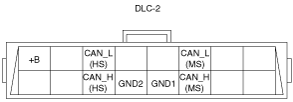
DLC-2 Outline
am3zzn00003180
|
|
Terminal name |
Function |
|---|---|
|
B+
|
Battery positive voltage
|
|
CAN_H (HS)
|
CAN communication line (HS)
|
|
CAN_L (HS)
|
CAN communication line (HS)
|
|
GND1
|
Ground (signal)
|
|
GND2
|
Ground (chassis)
|
|
CAN_H (MS)
|
CAN communication line (MS)
|
|
CAN_L (MS)
|
CAN communication line (MS)
|