 |
am2zzn00001553
ON-BOARD DIAGNOSTIC SYSTEM TEST MODE [MZ-CD 1.6 (Y6) (EURO5 emission level)]
id0102g7142500
|
Diagnostic test mode |
Item |
|---|---|
|
Mode 01
|
Sending diagnostic data (PID data monitor/On-board system readiness test)
|
|
Mode 02
|
Sending freeze frame data
|
|
Mode 03
|
Sending emission-related malfunction code (DTC)
|
|
Mode 04
|
Clearing/resetting emission-related malfunction information
|
|
Mode 06
|
Sending intermittent monitoring system test results (DMTR)
|
|
Mode 07
|
Sending continuous monitoring system test results (pending code)
|
|
Mode 09
|
Request vehicle information
|
Sending Diagnostic Data (Mode 01)
PID data monitor
PID/DATA monitor item table
|
Full names |
Unit |
|
|---|---|---|
|
Monitor status since DTCs cleared
|
No unit
|
|
|
LOAD
|
%
|
|
|
ECT
|
°C
|
°F
|
|
MAP
|
kPa
|
|
|
Engine speed
|
RPM
|
|
|
Vehicle speed
|
km/h
|
mph
|
|
IAT
|
°C
|
°F
|
|
MAF
|
g/s
|
|
|
Absolute throttle position
|
%
|
|
|
OBD requirement according to vehicle design
|
No unit
|
|
|
Time since engine start
|
s
|
|
|
Distance travelled while MIL is activated
|
km/h
|
mph
|
|
Fuel rail pressure
|
kPa
|
|
|
EGR valve control signal
|
%
|
|
|
Barometric pressure
|
kPa
|
|
|
Catalyst exhaust gas temperature sensor No.1
|
°C
|
°F
|
|
Ambient air temperature
|
°C
|
°F
|
|
APP from APP sensor No.1
|
%
|
|
|
APP from APP sensor No.2
|
%
|
|
|
Throttle actuator control signal
|
%
|
|
|
Time run by the engine while MIL is activated
|
hh : mm : ss
|
|
|
Engine run time since diagnostic trouble codes cleared
|
hh : mm : ss
|
|
Sending Freeze Frame Data/ Snapshot Data
Freeze frame data table
|
Freeze frame data item |
Unit |
Description |
Corresponding PID data monitor item |
|---|---|---|---|
|
LOAD
|
%
|
Calculated engine load
|
LOAD
|
|
ECT
|
°C
|
Engine coolant temperature
|
ECT
|
|
MAP
|
Pa
|
Manifold absolute pressure
|
MAP
|
|
RPM
|
RPM
|
Engine speed
|
RPM
|
|
VS
|
KPH
|
Vehicle speed
|
VSS
|
|
IAT
|
°C
|
Intake air temperature
|
IAT
|
|
MAF
|
g/sec
|
Mass airflow
|
MAF
|
|
TP
|
%
|
Throttle position sensor
|
TP1
|
|
RUNTM
|
hh : mm : ss
|
Time from engine start
|
—
|
|
FRP
|
Pa
|
Fuel pressure
|
FRP
|
|
BARO
|
Pa
|
Barometric pressure
|
BARO
|
|
APP_D
|
%
|
Accelerator pedal position No.1
|
APP1
|
Snapshot data table
|
Snapshot data item |
Unit |
Definition |
Corresponding PID data monitor item |
|---|---|---|---|
|
LOAD_C
|
%
|
Calculated engine load
|
—
|
|
ECT
|
°C
|
Engine coolant temperature
|
ECT
|
|
MAP
|
Pa
|
Manifold absolute pressure
|
MAP
|
|
RPM
|
RPM
|
Engine speed
|
RPM
|
|
VSS
|
KPH
|
Vehicle speed
|
VSS
|
|
IAT
|
°C
|
Intake air temperature
|
IAT
|
|
MAF
|
g/sec
|
Mass airflow
|
MAF
|
|
TP1
|
%
|
Throttle position sensor
|
TP1
|
|
EG_RUN_TIME
|
—
|
Time since engine start
|
—
|
|
FUEL_PRES
|
Pa
|
Fuel pressure sensor
|
FRP
|
|
SEGRP_DSD
|
%
|
Target EGR valve position
|
SEGRP DSD
|
|
BARO
|
Pa
|
Barometric pressure
|
BARO
|
|
AAT
|
°C
|
Ambient air temperature
|
AAT
|
|
APP1
|
%
|
Accelerator pedal position No.1
|
APP1
|
|
AAP2
|
%
|
Accelerator pedal position No.2
|
APP2
|
|
TOTAL_TIME
|
—
|
Total time
|
—
|
|
TOTAL_DIST
|
Km
|
Total distance
|
—
|
|
VPWR
|
V
|
Module supply voltage
|
—
|
|
ENG_STAT
|
Ready/ Running/ AFTERRUN
|
Engine status
|
ENG_STAT
|
|
CABIN_TEMP
|
°C
|
Cabin temperature
|
—
|
|
AAT
|
°C
|
Ambient air temperature
|
AAT
|
|
PWR_MODE_QF
|
Power Mode Undefined / Eval in Progress / Power Mode OK / Power Mode QF
|
Power mode quality factor
|
—
|
|
PWR_MODE_KEY
|
Key Out / Key Recently Out / Key Approved / Post Accessory / Accessory / Post Ignition / Ignition On / Running / Run-In Progress / Undefined
|
Power mode key state
|
—
|
Sending Emission-related Malfunction Code (DTC) (Mode 03)
|
DTC
|
Description
|
MIL
|
Powertrain warning light
|
Fuel in oil warning light
|
|
P0016:00
|
Crankshaft position - camshaft position correlation
|
-
|
ON
|
-
|
|
P0016:62
|
-
|
ON
|
-
|
|
|
P0045:00
|
Variable boost control (VBC) solenoid valve control circuit open
|
ON
|
-
|
-
|
|
P0047:00
|
Variable boost control (VBC) solenoid valve control circuit low input
|
ON
|
ON
|
-
|
|
P0048:00
|
Variable boost control (VBC) solenoid valve control circuit high input
|
ON
|
-
|
-
|
|
P0053:00
|
A/F sensor heater resistance
|
-
|
-
|
-
|
|
P0069:00
|
Manifold absolute pressure - barometric pressure correlation
|
ON
|
-
|
-
|
|
P0088:00
|
Fuel pressure - too high
|
-
|
ON
|
-
|
|
P0097:00
|
Boost air temperature sensor circuit low input
|
ON
|
-
|
-
|
|
P0098:00
|
Boost air temperature sensor circuit high input
|
ON
|
-
|
-
|
|
P0099:00
|
Boost air temperature sensor circuit intermittent/erratic
|
ON
|
-
|
-
|
|
P00BC:00
|
Mass air flow (MAF) sensor range/performance - airflow too low
|
ON
|
ON
|
-
|
|
P00BD:00
|
Mass air flow (MAF) sensor range/performance - airflow too high
|
ON
|
ON
|
-
|
|
P0101:00
|
Mass air flow (MAF) sensor circuit range/performance
|
ON
|
-
|
-
|
|
P0104:00
|
Mass air flow (MAF) sensor intermittent
|
ON
|
-
|
-
|
|
P0112:00
|
Intake air temperature (IAT) sensor circuit low input
|
ON
|
-
|
-
|
|
P0113:00
|
Intake air temperature (IAT) sensor circuit high input
|
ON
|
-
|
-
|
|
P0114:00
|
Intake air temperature (IAT) sensor circuit intermittent
|
ON
|
-
|
-
|
|
P0117:00
|
Engine coolant temperature (ECT) sensor circuit low input
|
ON
|
-
|
-
|
|
P0118:00
|
Engine coolant temperature (ECT) sensor circuit high input
|
ON
|
-
|
-
|
|
P0119:00
|
Engine coolant temperature (ECT) sensor circuit has intermittent malfunction or is erratic
|
ON
|
-
|
-
|
|
P0130:00
|
A/F sensor circuit open
|
-
|
-
|
-
|
|
P0131:00
|
A/F sensor circuit low
|
-
|
-
|
-
|
|
P0132:00
|
A/F sensor circuit high
|
-
|
-
|
-
|
|
P0135:11
|
A/F sensor heater circuit low
|
-
|
-
|
-
|
|
P0135:12
|
A/F sensor heater circuit high
|
-
|
-
|
-
|
|
P0135:13
|
A/F sensor heater circuit range/performance
|
-
|
-
|
-
|
|
P0135:98
|
A/F sensor heater circuit range/performance problem
|
-
|
-
|
-
|
|
P0172:00
|
Fuel system too rich
|
-
|
ON
|
-
|
|
P0182:00
|
Fuel temperature sensor circuit low input
|
-
|
-
|
-
|
|
P0183:00
|
Fuel temperature sensor circuit high input
|
-
|
-
|
-
|
|
P0184:00
|
Fuel temperature sensor circuit intermittent malfunction
|
-
|
-
|
-
|
|
P0191:00
|
Fuel pressure sensor circuit range/performance
|
-
|
ON
|
-
|
|
P0191:64
|
-
|
ON
|
-
|
|
|
P0192:00
|
Fuel pressure sensor circuit low input
|
-
|
ON
|
-
|
|
P0193:00
|
Fuel pressure sensor circuit high input
|
-
|
ON
|
-
|
|
P0194:00
|
Fuel pressure sensor circuit intermittent/erratic malfunction
|
-
|
ON
|
-
|
|
P0201:00
|
Fuel injector No.1 control circuit open
|
ON
|
ON
|
-
|
|
P0202:00
|
Fuel injector No.2 control circuit open
|
ON
|
ON
|
-
|
|
P0203:00
|
Fuel injector No.3 control circuit open
|
ON
|
ON
|
-
|
|
P0204:00
|
Fuel injector No.4 control circuit open
|
ON
|
ON
|
-
|
|
P0219:00
|
Engine overspeed condition
|
-
|
ON
|
-
|
|
P0234:00
|
Turbocharger over boost condition
|
ON
|
ON
|
-
|
|
P0234:85
|
ON
|
ON
|
-
|
|
|
P0236:00
|
Manifold absolute pressure (MAP) sensor signal gradient not compatible
|
ON
|
-
|
-
|
|
P0237:00
|
Manifold absolute pressure (MAP) sensor circuit low input
|
ON
|
-
|
-
|
|
P0238:00
|
Manifold absolute pressure (MAP) sensor circuit high input
|
ON
|
-
|
-
|
|
P0251:00
|
Fuel metering valve control circuit open
|
-
|
-
|
-
|
|
P0252:00
|
Fuel metering valve range/performance problem
|
-
|
ON
|
-
|
|
P0253:00
|
Fuel metering valve control circuit low input
|
-
|
-
|
-
|
|
P0254:00
|
Fuel metering valve control circuit high input
|
-
|
-
|
-
|
|
P0299:00
|
Turbocharger under boost condition
|
ON
|
-
|
-
|
|
P0299:84
|
ON
|
-
|
-
|
|
|
P029A:00
|
Cylinder No.1 - fuel trim at max limit
|
-
|
-
|
-
|
|
P029B:00
|
Cylinder No.1 - fuel trim at min limit
|
-
|
-
|
-
|
|
P029E:00
|
Cylinder No.2 - fuel trim at max limit
|
-
|
-
|
-
|
|
P029F:00
|
Cylinder No.2 - fuel trim at min limit
|
-
|
-
|
-
|
|
P02A2:00
|
Cylinder No.3 - fuel trim at max limit
|
-
|
-
|
-
|
|
P02A3:00
|
Cylinder No.3 - fuel trim at min limit
|
-
|
-
|
-
|
|
P02A6:00
|
Cylinder No.4 - fuel trim at max limit
|
-
|
-
|
-
|
|
P02A7:00
|
Cylinder No.4 - fuel trim at min limit
|
-
|
-
|
-
|
|
P02CC:00
|
Fuel injector No.1 offset learning at min limit
|
-
|
-
|
-
|
|
P02CD:00
|
Fuel injector No.1 offset learning at max limit
|
-
|
-
|
-
|
|
P02CE:00
|
Fuel injector No.2 offset learning at min limit
|
-
|
-
|
-
|
|
P02CF:00
|
Fuel injector No.2 offset learning at max limit
|
-
|
-
|
-
|
|
P02D0:00
|
Fuel injector No.3 offset learning at min limit
|
-
|
-
|
-
|
|
P02D1:00
|
Fuel injector No.3 offset learning at max limit
|
-
|
-
|
-
|
|
P02D2:00
|
Fuel injector No.4 offset learning at min limit
|
-
|
-
|
-
|
|
P02D3:00
|
Fuel injector No.4 offset learning at max limit
|
-
|
-
|
-
|
|
P02E1:00
|
Intake shutter valve control circuit range/performance malfunction
|
ON
|
-
|
-
|
|
P02E4:00
|
Intake shutter valve stuck open
|
ON
|
-
|
-
|
|
P02E5:00
|
Intake shutter valve stuck closed
|
ON
|
-
|
-
|
|
P02E8:00
|
Intake shutter valve position sensor circuit low input
|
ON
|
-
|
-
|
|
P02E9:00
|
Intake shutter valve position sensor circuit high input
|
ON
|
-
|
-
|
|
P02EA:00
|
Intake shutter valve position sensor circuit intermittent/erratic
|
ON
|
-
|
-
|
|
P02EB:00
|
Intake shutter valve actuator range/performance
|
ON
|
-
|
-
|
|
P02FA:28
|
Intake shutter valve position sensor minimum/maximum stop performance
|
-
|
-
|
-
|
|
P02FA:78
|
-
|
-
|
-
|
|
|
P0335:00
|
Crankshaft position (CKP) sensor circuit malfunction
|
-
|
ON
|
-
|
|
P0335:38
|
Crankshaft position (CKP) sensor circuit signal frequency incorrect
|
-
|
ON
|
-
|
|
P0336:00
|
Crankshaft position (CKP) sensor circuit range/performance
|
-
|
ON
|
-
|
|
P0339:00
|
Crankshaft position (CKP) sensor circuit intermittent
|
-
|
ON
|
-
|
|
P0340:00
|
Camshaft position (CMP) sensor circuit malfunction
|
-
|
ON
|
-
|
|
P0341:29
|
Camshaft position (CMP) sensor circuit range/performance - signal invalid
|
-
|
ON
|
-
|
|
P0341:37
|
Camshaft position (CMP) sensor circuit range/performance - signal frequency to high
|
-
|
ON
|
-
|
|
P0341:62
|
Camshaft position (CMP) sensor circuit range/performance - signal compare failure
|
-
|
ON
|
-
|
|
P037D:00
|
Glow plug control circuit malfunction
|
-
|
-
|
-
|
|
P0383:00
|
Glow plug control circuit low input
|
-
|
-
|
-
|
|
P0384:00
|
Glow plug control circuit high input
|
-
|
-
|
-
|
|
P0404:00
|
EGR valve control circuit range/performance malfunction
|
ON
|
-
|
-
|
|
P0405:00
|
EGR valve position sensor circuit low input
|
ON
|
-
|
-
|
|
P0406:00
|
EGR valve position sensor circuit high input
|
ON
|
-
|
-
|
|
P042E:00
|
EGR valve stuck open
|
ON
|
ON
|
-
|
|
P042F:00
|
EGR valve stuck closed
|
ON
|
-
|
-
|
|
P0504:00
|
Brake switch signal correlation
|
-
|
ON
|
-
|
|
P0531:00
|
Refrigerant pressure sensor circuit range/performance
|
-
|
-
|
-
|
|
P0532:00
|
Refrigerant pressure sensor circuit low input
|
-
|
-
|
-
|
|
P0533:00
|
Refrigerant pressure sensor circuit high input
|
-
|
-
|
-
|
|
P0545:00
|
Exhaust gas temperature sensor No.1 circuit low input
|
ON
|
-
|
-
|
|
P0546:00
|
Exhaust gas temperature sensor No.1 circuit high input
|
ON
|
-
|
-
|
|
P0562:00
|
System voltage too low
|
-
|
-
|
-
|
|
P0563:00
|
System voltage too high
|
-
|
-
|
-
|
|
P0564:83
|
Cruise control multi function input
|
-
|
-
|
-
|
|
P0606:00
|
PCM internal processor malfunction
|
ON
|
ON
|
-
|
|
P060A:00
|
Internal control module monitoring processor malfunction
|
-
|
ON
|
-
|
|
P060B:00
|
Internal control module A/D processing performance
|
-
|
ON
|
-
|
|
P060D:00
|
Internal control module accelerator pedal position performance
|
-
|
ON
|
-
|
|
P0617:00
|
Main relay control circuit high
|
-
|
-
|
-
|
|
P061A:00
|
Internal control module torque performance
|
-
|
ON
|
-
|
|
P061B:00
|
Internal control module torque calculation performance
|
-
|
-
|
-
|
|
P061B:01
|
-
|
-
|
-
|
|
|
P061C:00
|
Internal control module engine RPM performance
|
-
|
ON
|
-
|
|
P062B:00
|
Internal control module fuel injector control performance
|
-
|
ON
|
-
|
|
P062B:04
|
Internal control module fuel injector control performance - system internal failures
|
-
|
-
|
-
|
|
P062B:64
|
Internal control module fuel injector control performance - signal plausibility failure
|
-
|
-
|
-
|
|
P062D:00
|
Fuel injector driver circuit performance problem
|
-
|
ON
|
-
|
|
P0642:00
|
Sensor reference circuit low input
|
ON
|
ON
|
-
|
|
P0643:00
|
Sensor reference circuit high input
|
ON
|
ON
|
-
|
|
P0645:00
|
A/C relay circuit open
|
-
|
-
|
-
|
|
P0646:00
|
A/C relay circuit low input
|
-
|
-
|
-
|
|
P0647:00
|
A/C relay circuit high input
|
-
|
-
|
-
|
|
P064D:00
|
Internal control module A/F sensor processor performance
|
-
|
-
|
-
|
|
P064D:67
|
-
|
-
|
-
|
|
|
P0652:00
|
Sensor reference circuit low input
|
-
|
ON
|
-
|
|
P0653:00
|
Sensor reference circuit high input
|
-
|
ON
|
-
|
|
P0667:00
|
PCM internal temperature sensor range/performance
|
-
|
-
|
-
|
|
P0668:00
|
PCM internal temperature sensor circuit low
|
-
|
-
|
-
|
|
P0669:00
|
PCM internal temperature sensor circuit high
|
-
|
-
|
-
|
|
P0670:00
|
Glow plug control circuit open
|
-
|
-
|
-
|
|
P0691:00
|
Cooling fan control circuit low
|
-
|
-
|
-
|
|
P0691:13
|
-
|
-
|
-
|
|
|
P0692:00
|
Cooling fan control circuit high
|
-
|
-
|
-
|
|
P0698:00
|
Sensor reference circuit low input
|
-
|
ON
|
-
|
|
P0699:00
|
Sensor reference circuit high input
|
-
|
ON
|
-
|
|
P0830:00
|
Clutch pedal position (CPP) switch circuit malfunction
|
-
|
-
|
-
|
|
P0A09:00
|
DC-DC converter circuit low
|
ON
|
-
|
-
|
|
P0A10:00
|
DC-DC converter circuit high
|
ON
|
-
|
-
|
|
P1131:00
|
Lack of A/F sensor - sensor indicates lean
|
-
|
-
|
-
|
|
P115A:00
|
Low fuel level - forced limited power
|
-
|
ON
|
-
|
|
P115B:00
|
Low fuel level - forced engine shutdown
|
-
|
ON
|
-
|
|
P1193:00
|
EGR driver over current
|
ON
|
-
|
-
|
|
P1200:00
|
Fuel injector range/performance
|
-
|
ON
|
-
|
|
P1261:00
|
Fuel injector No.1 circuit high to low side short
|
ON
|
ON
|
-
|
|
P1262:00
|
Fuel injector No.2 circuit high to low side short
|
ON
|
ON
|
-
|
|
P1263:00
|
Fuel injector No.3 circuit high to low side short
|
ON
|
ON
|
-
|
|
P1264:00
|
Fuel injector No.4 circuit high to low side short
|
ON
|
ON
|
-
|
|
P1295:00
|
Fuel injector multiple faults
|
ON
|
ON
|
-
|
|
P1303:28
|
EGR calibration fault
|
-
|
-
|
-
|
|
P1303:78
|
-
|
-
|
-
|
|
|
P1335:00
|
EGR valve position sensor minimum/maximum stop performance
|
-
|
ON
|
-
|
|
P138E:00
|
Wastegate valve actuator position sensor maximum stop performance
|
-
|
-
|
-
|
|
P138E:28
|
Wastegate valve actuator position sensor minimum stop performance
|
-
|
-
|
-
|
|
P138E:29
|
Wastegate valve actuator position sensor maximum stop performance
|
-
|
-
|
-
|
|
P138E:78
|
Wastegate valve actuator position sensor minimum stop performance
|
-
|
-
|
-
|
|
P141A:00
|
EGR position sensor signal -intermittent fault
|
ON
|
-
|
-
|
|
P1563:00
|
Supply pump control module requesting engine stop
|
ON
|
ON
|
-
|
|
P1593:00
|
Cruise control monitor fault
|
-
|
ON
|
-
|
|
P1632:09
|
Generator fault
|
-
|
-
|
-
|
|
P1632:49
|
-
|
-
|
-
|
|
|
P1632:98
|
-
|
-
|
-
|
|
|
P1642:00
|
CAN Link PCM/PCM Circuit/Network problem
|
-
|
ON
|
-
|
|
P169F:00
|
Control module malfunction
|
-
|
-
|
-
|
|
P193A:00
|
Invalid scan tool communication/request
|
-
|
-
|
-
|
|
P1A08:00
|
Generator fault
|
-
|
-
|
-
|
|
P2002:00
|
Diesel particulate filter efficiency below threshold
|
ON
|
ON
|
-
|
|
P2032:00
|
Exhaust gas temperature sensor No.2 circuit low input
|
ON
|
-
|
-
|
|
P2033:00
|
Exhaust gas temperature sensor No.2 circuit high input
|
ON
|
-
|
-
|
|
P2081:00
|
Exhaust gas temperature sensor No.1 circuit intermittent
|
ON
|
-
|
-
|
|
P2085:00
|
Exhaust gas temperature sensor No.2 circuit intermittent
|
ON
|
-
|
-
|
|
P2122:00
|
Accelerator pedal position (APP) sensor No.1 signal - low
|
-
|
ON
|
-
|
|
P2123:00
|
Accelerator pedal position (APP) sensor No.1 signal - high
|
-
|
ON
|
-
|
|
P2127:00
|
Accelerator pedal position (APP) sensor No.2 signal - low
|
-
|
ON
|
-
|
|
P2128:00
|
Accelerator pedal position (APP) sensor No.2 signal - high
|
-
|
ON
|
-
|
|
P2138:00
|
Accelerator pedal position (APP) sensor No.1/No.2 position correlation
|
-
|
ON
|
-
|
|
P2227:00
|
BARO sensor range/performance problem
|
ON
|
-
|
-
|
|
P2228:00
|
BARO sensor circuit low input
|
ON
|
-
|
-
|
|
P2229:00
|
BARO sensor circuit high input
|
ON
|
-
|
-
|
|
P2237:00
|
A/F sensor positive current control circuit open
|
-
|
-
|
-
|
|
P2238:00
|
A/F sensor positive current control low
|
-
|
-
|
-
|
|
P2243:00
|
A/F sensor reference voltage circuit open
|
-
|
-
|
-
|
|
P226B:00
|
Manifold absolute pressure to high - mechanical
|
-
|
ON
|
-
|
|
P228C:00
|
Fuel pressure regulator exceeded control limits - pressure too low
|
-
|
ON
|
-
|
|
P228C:7B
|
-
|
ON
|
-
|
|
|
P228D:00
|
Fuel pressure regulator exceeded control limits - pressure too high
|
-
|
ON
|
-
|
|
P2291:00
|
Fuel pressure too low - engine cranking
|
-
|
-
|
-
|
|
P2297:00
|
A/F sensor out of range during deceleration
|
-
|
-
|
-
|
|
P2414:00
|
A/F sensor exhaust sample error
|
-
|
-
|
-
|
|
P2425:00
|
EGR cooler bypass valve solenoid valve control circuit open
|
-
|
-
|
-
|
|
P244A:00
|
Diesel particulate filter differential pressure to low
|
ON
|
ON
|
-
|
|
P244B:00
|
Diesel particulate filter differential pressure to high
|
ON
|
ON
|
-
|
|
P244D:00
|
Exhaust temperature too high for diesel particulate filter regeneration
|
-
|
ON
|
-
|
|
P2453:84
|
Diesel particulate filter differential pressure sensor range/performance problem
|
ON
|
ON
|
-
|
|
P2453:85
|
Diesel particulate filter differential pressure sensor range/performance problem
|
ON
|
ON
|
-
|
|
P2454:00
|
Diesel particulate filter differential pressure sensor circuit low input
|
ON
|
ON
|
-
|
|
P2455:00
|
Diesel particulate filter differential pressure sensor circuit high input
|
ON
|
ON
|
-
|
|
P2456:00
|
Diesel particulate filter differential pressure sensor intermittent/erratic
|
ON
|
ON
|
-
|
|
P2457:16
|
EGR cooler bypass valve position sensor circuit low
|
-
|
-
|
-
|
|
P2457:17
|
EGR cooler bypass valve position sensor circuit high
|
-
|
-
|
-
|
|
P245B:00
|
EGR cooler bypass valve solenoid valve control circuit range/performance problem
|
-
|
-
|
-
|
|
P245C:00
|
EGR cooler bypass valve solenoid valve control circuit low input
|
-
|
-
|
-
|
|
P245D:00
|
EGR cooler bypass valve solenoid valve control circuit high input
|
-
|
-
|
-
|
|
P2463:00
|
Diesel particulate filter restriction
|
ON
|
-
|
-
|
|
P246C:00
|
ON
|
ON
|
-
|
|
|
P253F:00
|
Engine oil deteriorated
|
-
|
ON
|
ON
|
|
P2544:00
|
Torque management request input signal
|
-
|
-
|
-
|
|
P2564:00
|
Wastegate valve actuator position sensor circuit low input
|
ON
|
-
|
-
|
|
P2565:00
|
Wastegate valve actuator position sensor circuit high input
|
ON
|
-
|
-
|
|
P2566:00
|
Wastegate valve actuator position sensor circuit intermittent
|
ON
|
-
|
-
|
|
P2598:00
|
VBC solenoid valve stuck open
|
ON
|
ON
|
-
|
|
P2599:00
|
VBC solenoid valve stuck closed
|
ON
|
ON
|
-
|
|
U0120:00
|
Lost communication with generator
|
-
|
-
|
-
|
|
U0120:02
|
Lost communication with generator - signal failure
|
-
|
-
|
-
|
|
U0415:00
|
Invalid data received from DSC CM
|
ON
|
-
|
-
|
|
U0426:00
|
Immobilizer system - invalid data received from immobilizer control module
|
-
|
-
|
-
|
|
U1A35:86
|
VIN data - signal invalid
|
-
|
ON
|
-
|
|
U1A35:87
|
VIN data - missing message
|
-
|
ON
|
-
|
|
U2101:00
|
Control module configuration incompatible
|
-
|
ON
|
-
|
Sending Continuous Monitoring System Test Results
1-drive cycle type
2-drive cycle type
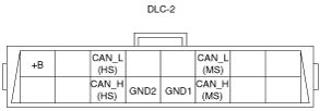
DLC-2 Outline
am2zzn00001553
|
|
Terminal name |
Function |
|---|---|
|
B+
|
Battery positive voltage
|
|
CAN_H (HS)
|
CAN communication line (HS)
|
|
CAN_L (HS)
|
CAN communication line (HS)
|
|
GND1
|
Ground (chassis)
|
|
GND2
|
Ground (signal)
|
|
CAN_H (MS)
|
CAN communication line (MS)
|
|
CAN_L (MS)
|
CAN communication line (MS)
|