|
1
|
VERIFY FREEZE FRAME DATA HAS BEEN RECORDED
• Has the FREEZE FRAME DATA been recorded?
|
Yes
|
Go to the next step.
|
|
No
|
Record FREEZE FRAME DATA on repair order, then go to the next step.
|
|
2
|
VERIFY RELATED SERVICE INFORMATION AVAILABILITY
• Verify related service information availability.
• Is any related service information available?
|
Yes
|
Perform repair or diagnosis according to available service information.
• If vehicle is not repaired, go to the next step.
|
|
No
|
Go to the next step.
|
|
3
|
VERIFY RELATED PENDING CODE AND/OR DTC
• Switch the ignition to ON (engine off).
• Perform the Pending Trouble Code Access Procedure and DTC Reading Procedure.
• Is the other PENDING CODE/DTC also present?
|
Yes
|
Go to the applicable DTC inspection.
|
|
No
|
Go to the next step.
|
|
4
|
VISUALLY INSPECT CMP SENSOR INSTALLATION
• Switch the ignition to OFF.
• Visually inspect the CMP sensor installation.
• Is there a mis-installation or foreign matter adhering to the detection area?
|
Yes
|
Install correctly or remove the foreign matter, then go to Step 10.
|
|
No
|
Go to the next step.
|
|
5
|
INSPECT CMP SENSOR PULSE WHEEL
• Visually inspect the CMP sensor pulse wheel (camshaft pulley).
• Is there any malfunction?
|
Yes
|
Replace the camshaft pulley, then go to Step 10.
|
|
No
|
Go to the next step.
|
|
6
|
INSPECT CMP SENSOR CIRCUIT FOR SHORT TO GROUND CIRCUIT
• Disconnect the CMP sensor connector.
• Inspect for continuity between each CMP sensor terminals (wiring harness-side) and body ground.
• Is there any continuity?
|
Yes
|
If the short to ground circuit could be detected:
• Repair or replace the wiring harness for a possible short to ground.
If the short to ground circuit could not be detected:
• Replace the PCM (short to ground in PCM internal circuit).
Go to Step 10.
|
|
No
|
Go to the next step.
|
|
7
|
INSPECT CMP SENSOR CIRCUIT FOR SHORT TO POWER SUPPLY CIRCUIT
• CMP sensor connector is disconnected.
• Switch the ignition to ON (engine off).
• Disconnect the PCM connector.
• Measure the voltage between each CMP sensor terminals (wiring harness-side) and body ground.
• Is the voltage B+?
|
Yes
|
Repair or replace the wiring harness for a possible short to power supply circuit, then go to Step 10.
|
|
No
|
Go to the next step.
|
|
8
|
INSPECT CMP SENSOR CIRCUIT FOR OPEN CIRCUIT
• Switch the ignition to OFF.
• CMP sensor and PCM connectors are disconnected.
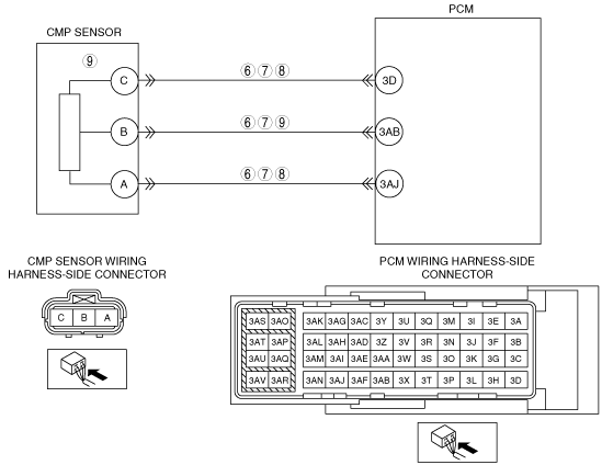
• Inspect for continuity between the following terminals (wiring harness-side):
-
― CMP sensor terminal A—PCM terminal 3AJ
― CMP sensor terminal B—PCM terminal 3AB
― CMP sensor terminal C—PCM terminal 3D
• Is there continuity?
|
Yes
|
Go to the next step.
|
|
No
|
Repair or replace the wiring harness for a possible open circuit, then go to Step 10.
|
|
9
|
INSPECT CMP SENSOR
• Inspect the CMP sensor.
• Is there any malfunction?
|
Yes
|
Replace the CMP sensor, then go to Step.
|
|
No
|
Intermittent concern exists.
Go to the next step.
|
|
10
|
VERIFY THAT DTC P0340:00 TROUBLESHOOTING IS COMPLETED
• Make sure to reconnect all disconnected connectors.
• Clear the DTC from the memory using the M-MDS.
• Run the vehicle under the FREEZE FRAME DATA stored condition.
• Is the same DTC present?
|
Yes
|
Replace the PCM, then go to the next step.
|
|
No
|
Go to the next step.
|
|
11
|
VERIFY AFTER REPAIR PROCEDURE
• Perform the “After Repair Procedure“.
• Are any DTCs present?
|
Yes
|
Go to the applicable DTC inspection.
|
|
No
|
DTC troubleshooting completed.
|