 |
am3uun00000327
VARIABLE VALVE TIMING MECHANISM CONSTRUCTION [LF, L5]
id0110a7118000
am3uun00000327
|
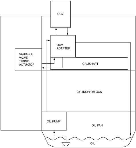
Hydraulic Pressure Flow Diagram
am6xun00000654
|
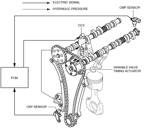
Component and Function
|
Variable valve timing actuator
|
• The phase difference between the variable timing actuator and camshaft on the intake side changes continually based on the hydraulic pressure controlled by the OCV.
|
|
OCV
|
• Operated by current (duty signal) from the PCM. Switches the hydraulic oil passages to the variable valve timing actuator.
|
|
CKP sensor
|
• Inputs crankshaft position signal to the PCM.
|
|
CMP sensor
|
• Inputs camshaft position signal to the PCM.
|
|
PCM
|
• Controls the OCV so that optimum valve timing is obtained according to engine operation conditions.
|