OIL CONTROL VALVE (OCV) REMOVAL/INSTALLATION [ZY, Z6]


id0110b0801300

1.  Remove the battery cover. (See BATTERY REMOVAL/INSTALLATION [ZY, Z6].)

2.  Disconnect the negative battery cable.

3.  Perform the following procedure.

Except European (U.K.) specs.
1.  Remove the fresh-air duct and the air cleaner as a single unit. (See INTAKE-AIR SYSTEM REMOVAL/INSTALLATION [ZY, Z6].)
European (U.K.) specs.
1.  Set the air cleaner cover out of the way. (See INTAKE-AIR SYSTEM REMOVAL/INSTALLATION [ZY, Z6].)
2.  Remove the fresh-air duct and the air cleaner case as a single unit. (See INTAKE-AIR SYSTEM REMOVAL/INSTALLATION [ZY, Z6].)

4.  Remove the dipstick.

5.  Remove the coolant reserve tank with the hoses still connected. (See COOLANT RESERVE TANK REMOVAL/INSTALLATION [ZY, Z6].)

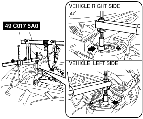
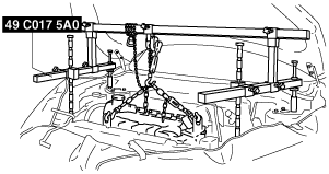
6.  Install the SST using the following procedure.

Caution
•  Refer to the SST instruction manual for the basic handing procedure.
am3zzw00006904
(1)  Remove the brake vacuum hose bracket bolt, then set the brake vacuum hose bracket out of the way.
am3zzw00006900
(2)  Set the fuel pipe bracket out of the way to prevent interference with the SST as shown in the figure.
am3zzw00008592
(3)  Using the bolts part number 99794 1025 or M10× 1.25, length 25 mm {0.98 in} to install the SST to the position as shown in the figure.
am2zzw00000190
Tightening torque
38—51 N·m {3.9—5.2 kgf·m, 29—37 ft·lbf}
(4)   Remove the installation bolt for the bracket securing the lower radiator hose.
am3uuw00005082
(5)  Set the cooler pipe aside to prevent it from interfering with the front shaft of the SST. (right side)
(6)  As shown in the figure, set the rear shafts of the SST to the left and right shock absorber bolts.
am3zzw00008807
(7)  Install front foot No.2 to the left/right front shaft of the SST, then align the groove of the front shaft of the SST with the folded up part of the vehicle as shown in the figure.
am3zzw00008808
(8)  Adjust the positions of the SST side bars so that they are the same height (left and right) and horizontal. Make sure each joint is securely tightened.
am3zzw00005429
(9)  Apply tension to the chain to secure the engine.

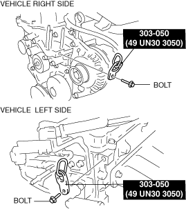
7.  Disconnect the ground cable from the No.3 engine mount.

8.  Remove the No.3 engine mount. (See TIMING CHAIN REMOVAL/INSTALLATION [ZY, Z6].)

9.  Disconnect the OCV connector.
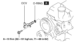
10.  Remove the OCV.

am3zzw00006907

11.  Install the new O-ring.

12.  Install the OCV.

13.  Connect the OCV connector.

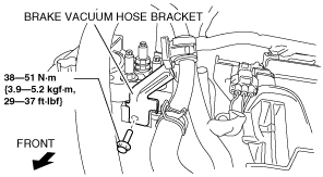
14.  Tighten the No.3 engine mount installation stud bolts.

am3zzw00006908

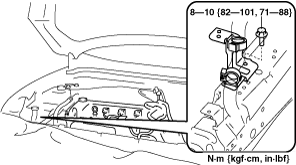
15.  Install the No.3 engine mount, and then temporarily tighten the installation bolts and nuts.

Note
•  Do not tighten the bolts and nuts during this step.

16.  Tighten the installation bolts and nuts in the order shown in the figure.

am3zzw00006909

Tightening torque
1 (nuts): 44—61 N·m {4.5—6.2 kgf·m, 33—44 ft·lbf}
2 (bolts): 71—93 N·m {7.3—9.4 kgf·m, 53—68 ft·lbf}

17.  Install the ground cable to the No.3 engine mount.

Tightening torque
35—50 N·m {3.6—5.0 kgf·m, 26—36 ft·lbf}

18.  Remove the SSTs.

19.  Install in the reverse order of removal.