SUPPLY PUMP CONSTRUCTION/OPERATION [MZ-CD 1.6 (Y6)]


id0114c3102700


EURO4 Emission Level

•  The supply pump is made up of a fuel transfer pump and a high-pressure fuel delivery pump.
am2zzn00001208

Fuel transfer pump operation

•  The fuel transfer pump works using two meshed gears. One gear is driven by the input shaft. The fuel is carried between the teeth of the gears and the fuel transfer pump casing. The amount of fuel the fuel transfer pump can deliver to the high-pressure fuel pump chambers is dependent on engine speed. But at the minimum transfer rate, a larger than required quantity of fuel is available. Excess fuel from the fuel transfer pump is returned to the fuel tank through the fuel return line manifold.
•  The amount of fuel allowed to enter the high-pressure fuel pump chambers from the fuel transfer pump is controlled by the fuel metering valve. Controlling the fuel volume input to the high-pressure pump chambers, directly controls the fuel pressure output from the high-pressure pump. The developed high-pressure fuel supply is monitored by the fuel pressure sensor mounted on the common rail. The PCM uses the signal from the fuel pressure sensor to calculate the flow rate through the fuel metering valve.
•  During the development of high-pressure fuel supply, large amounts of heat are generated. The excess fuel returned to the fuel tank assists with the cooling and lubrication of the high-pressure fuel pump components.
am2zzn00001213


High-pressure fuel development

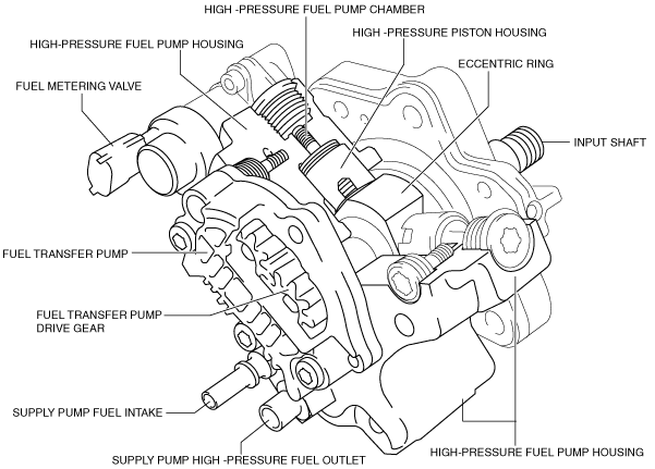
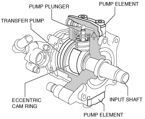
•  The high-pressure fuel pump is driven by the timing belt through the input shaft. The input shaft rotates an eccentric lobe within the eccentric ring. The eccentric ring is forced against the high-pressure pistons to produce the high pressure fuel supply.
•  During each revolution of the input shaft, all three high-pressure fuel pump chambers will deliver pressurized fuel to the common rail.
•  During the high-pressure fuel development stage, fuel in the high-pressure fuel pump chamber is compressed by the high-pressure piston until the pressure in the fuel pump high-pressure chamber exceeds the fuel pressure in the common rail. At this point the high-pressure fuel outlet valve opens and allows fuel to be delivered to the common rail. As the high-pressure piston reaches the end of its compression stroke, the fuel pressure in the common rail and the fuel pump chamber equalize.
•  As the eccentric ring rotates, the high-pressure piston will retract from the high-pressure chamber under the force of the high-pressure piston return spring. The fuel pressure in the common rail will become greater than the fuel pressure in the high-pressure chamber. This will make the high-pressure fuel outlet valve close, so maintaining the fuel pressure in the common rail.
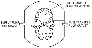
•  When the fuel pressure in the high-pressure chamber drops below the fuel pressure developed by the fuel transfer pump, the high-pressure chamber fuel intake valve will open and allow fuel to be delivered from the fuel transfer pump to the high-pressure chamber. The fuel transfer pump will continue to deliver fuel to the high-pressure chamber until the high-pressure fuel development stage has started and the developing fuel pressure in the high-pressure chamber exceeds the fuel pressure of the transfer pump at which point the high-pressure chamber fuel intake valve will close.
am2zzn00001209


EURO5 Emission Level


Construction

•  The supply pump is driven via the timing belt for the camshaft drive.
am3zzn00003472
•  The two pump elements for generating high pressure are positioned with a radial offset of 180°. The drive for the pump plunger is provided via an eccentric cam which is permanently connected to the input shaft.
•  The eccentric cam on the input shaft actuates both of the pump elements one after the other. The creation of high pressure occurs in synchronization with the intake stroke of the particular engine cylinder. The supply pump for each engine cylinder therefore always delivers at the same crankshaft angle.
•  Because of this, pressure variations in the high-pressure area are minimized and fuel metering is therefore made even more precise.
Pressure relief valve
•  A pressure relief valve is integrated inside the supply pump.
•  This serves as a safety device protecting against excess fuel pressure if a malfunction occurs in the system (such as fuel metering valve is stuck open).
•  If the fuel pressure exceeds the threshold value, the pressure relief valve opens and the fuel can escape to the inner chamber of the supply pump.


Operation

•  The fuel is drawn from the fuel tank via the fuel filter by means of the transfer pump integrated in the supply pump.
•  The transfer pump delivers the fuel to the fuel metering valve and to the lubrication valve. When the fuel metering valve is closed, the admission pressure control valve opens and routes the excess fuel back to the intake side of the transfer pump.
•  The lubrication valve is calibrated so as to always ensure sufficient lubrication and cooling in the interior of the pump.
•  The fuel quantity fed to the high pressure chambers (pump elements) is determined via the electromagnetically operated fuel metering valve.
•  The high pressure outputs of the two pump elements are brought together and fed to the high pressure output of the supply pump.
am5ezn00002088
Principle of high-pressure generation (intake stroke)
•  The pump plungers are actuated by the rotary movement of the supply pump input shaft and the eccentric cam which sits on the shaft.
•  The fuel pressure is then transferred from the transfer pump via the fuel metering valve to the intake valves of the high pressure chambers. If the transfer pressure exceeds the internal pressure of the high pressure chamber (pump plunger in TDC (top dead center) position), the inlet valve opens.
•  Fuel is then forced into the high pressure chamber and the pump plunger moves downwards (intake stroke).
Principle of high-pressure generation (delivery stroke)
•  When the pump plunger passes bottom dead center (BDC), the inlet valve closes due to the increasing pressure in the high-pressure chamber and the fuel in the high-pressure chamber can no longer escape.
•  As soon as the pressure in the high-pressure chamber exceeds the pressure in the high-pressure channel, the outlet valve opens and the fuel is forced into the high-pressure channel (delivery stroke).
•  The pump plunger delivers fuel until top dead center (TDC) is reached. The pressure then drops and the outlet valve closes.
•  The pressure on the remaining fuel is reduced and the pump plunger moves downwards.
•  If the pressure in the high-pressure chamber falls below the transfer pressure, the inlet valve reopens and the process starts again.
am3zzn00003473