 |
am3zzw00016366
CURRENT SENSOR INSPECTION [MZR 2.0 DISI i-stop]
id0140j1805300
Current Sensor No.1
1. Inspect the battery. (See BATTERY INSPECTION [MZR 2.0 DISI i-stop].)
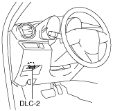
2. Connect the M-MDS to the DLC-2.
am3zzw00016366
|
3. Switch the ignition to ON.
4. Verify that the more the electrical load is increased, the lower the current sensor No.1 output voltage (PID: ALT_CUR_S). (See PCM INSPECTION [MZR 2.0 DISI i-stop].)
5. Verify that the current sensor No.1 output voltage (PID: ALT_CUR_S) with no load is within the specification. (See PCM INSPECTION [MZR 2.0 DISI i-stop].)
Current Sensor No.2
1. Inspect the battery. (See BATTERY INSPECTION [MZR 2.0 DISI i-stop].)
2. Turn off all electrical loads.
3. Inspect the current sensor No.1. (See Current Sensor No.1.)
4. Turn on the headlights (LO) and record the detection current value of the current sensor No.1 (PID: BATT_CUR).
5. Calculate the power consumption (subtract the value recorded in Step 4 from the value recorded in Step 3).
6. Disconnect the negative battery cable from the main and sub batteries.
7. Connect the negative battery cable of the sub battery to the main battery.
8. Switch the ignition to ON.
9. Verify that the more the electrical load is increased, the lower the current sensor No.2 output voltage (PID: BATT_B_CUR, unit V). (See PCM INSPECTION [MZR 2.0 DISI i-stop].)
10. Verify that the current sensor No.2 (PID: BATT_B_CUR, unit A) with no load is within the specification. (See PCM INSPECTION [MZR 2.0 DISI i-stop].)
11. Turn on the headlights (LO) and record the detection current value of the current sensor No.2 (PID: BATT_B_CUR, unit A).
12. Calculate the power consumption (subtract the value recorded in Step 11 from the value recorded in Step 10).
13. Verify that the difference between the power consumptions calculated in Steps 5 and 12 is within 3A.
14. Display the DTC using the M-MDS.(See ON-BOARD DIAGNOSTIC TEST [MZR 2.0 DISI i-stop].)