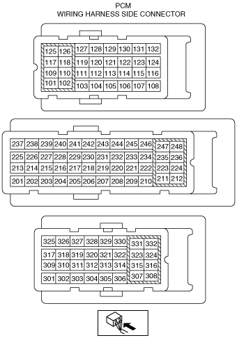
 |
am3zzw00008135
PCM INSPECTION [MZ-CD 1.6 (Y6) (EURO4 emission level)]
id0140j5802500
am3zzw00008135
|
PCM terminal voltage table (Reference)
|
Terminal |
Signal name |
Connected to |
Measurement condition |
Voltage (V) |
Inspection item(s) |
|---|---|---|---|---|---|
|
101
|
Fuel injector No.1 control signal “high”
|
Fuel injector No.1
|
• Fuel injector No.1
• Related wiring harness
|
||
|
102
|
Fuel injector No.4 control signal “high”
|
Fuel injector No.4
|
• Fuel injector No.4
• Related wiring harness
|
||
|
103
|
Fuel temperature sensor ground
|
Fuel temperature sensor
|
Under any condition
|
1.0 or less
|
• Fuel temperature sensor
• Related wiring harness
|
|
104
|
Variable boost control signal
|
Variable boost control solenoid valve
|
• Variable boost control solenoid valve
• Related wiring harness
|
||
|
105
|
Sensor ground
|
Air bypass valve position sensor, EGR throttle valve position sensor
|
Under any condition
|
1.0 or less
|
• Related wiring harness
|
|
106
|
—
|
||||
|
107
|
Generator command
|
Generator
|
• Generator
• Related wiring harness
|
||
|
108
|
Starter control signal
|
Starter relay
|
Under any condition
|
1.0 or less
|
• Starter relay
• Related wiring harness
|
|
109
|
Fuel injector No.3 control signal “high”
|
Fuel injector No.3
|
• Fuel injector No.3
• Related wiring harness
|
||
|
110
|
Fuel injector No.2 control signal “high”
|
Fuel injector No.2
|
• Fuel injector No.2
• Related wiring harness
|
||
|
111
|
—
|
||||
|
112
|
A/C control signal
|
A/C relay
|
Under any condition
|
1.0 or less
|
• A/C relay
• Related wiring harness
|
|
113
|
—
|
||||
|
114
|
Catalyst exhaust gas temperature sensor ground
|
Catalyst exhaust gas temperature sensor
|
Under any condition
|
1.0 or less
|
• Catalyst exhaust gas temperature sensor
• Related wiring harness
|
|
115
|
—
|
||||
|
116
|
—
|
||||
|
117
|
Fuel injector No.4 control signal “low”
|
Fuel injector No.4
|
• Fuel injector No.4
• Related wiring harness
|
||
|
118
|
Fuel injector No.1 control signal “low”
|
Fuel injector No.1
|
• Fuel injector No.1
• Related wiring harness
|
||
|
119
|
Diesel particulate filter differential pressure sensor ground
|
Diesel particulate filter differential pressure sensor
|
Under any condition
|
1.0 or less
|
• Diesel particulate filter differential pressure sensor
• Related wiring harness
|
|
120
|
—
|
||||
|
121
|
EGR valve position sensor ground
|
EGR valve position sensor
|
Under any condition
|
1.0 or less
|
• EGR valve position sensor
• Related wiring harness
|
|
122
|
—
|
||||
|
123
|
—
|
||||
|
124
|
—
|
||||
|
125
|
Fuel injector No.3 control signal “low”
|
Fuel injector No.3
|
• Fuel injector No.3
• Related wiring harness
|
||
|
126
|
Fuel injector No.2 control signal “low”
|
Fuel injector No.2
|
• Fuel injector No.2
• Related wiring harness
|
||
|
127
|
—
|
||||
|
128
|
—
|
||||
|
129
|
EGR valve position sensor signal
|
EGR valve position sensor
|
Switch the ignition off
|
1.0 or less
|
• EGR valve
• Related wiring harness
|
|
Switch the ignition ON
|
Approx. 1.0
|
||||
|
Idle
|
Approx. 3.7
|
||||
|
130
|
—
|
||||
|
131
|
—
|
||||
|
132
|
Glow time feed back input signal state
|
Glow plug relay
|
Glow plug relay ON
|
B+
|
• Glow plug relay
• Related wiring harness
|
|
Glow plug relay off
|
1.0 or less
|
||||
|
201
|
EGR valve position sensor supply
|
EGR valve position sensor
|
Switch the ignition ON
|
Approx. 5.0
|
• EGR valve
• Related wiring harness
|
|
202
|
Fuel pressure sensor supply
|
Fuel pressure sensor
|
Switch the ignition ON
|
Approx. 5.0
|
• Fuel pressure sensor
• Related wiring harness
|
|
203
|
Fuel pressure sensor ground
|
Fuel pressure sensor
|
Under any condition
|
1.0 or less
|
• Fuel pressure sensor
• Related wiring harness
|
|
204
|
MAP sensor ground
|
MAP sensor
|
Under any condition
|
1.0 or less
|
• MAP sensor
• Related wiring harness
|
|
205
|
MAP sensor supply
|
MAP sensor
|
Switch the ignition ON
|
Approx. 5.0
|
• MAP sensor
• Related wiring harness
|
|
206
|
Constant voltage (Vref)
|
CMP sensor, EGR throttle valve position sensor, air bypass valve position sensor
|
Switch the ignition ON
|
Approx. 5.0
|
• Related wiring harness
|
|
207
|
Diesel particulate filter differential pressure sensor supply
|
Diesel particulate filter differential pressure sensor
|
Switch the ignition ON
|
Approx. 5.0
|
• Diesel particulate filter differential pressure sensor
• Related wiring harness
|
|
208
|
—
|
||||
|
209
|
—
|
||||
|
210
|
Glow plug control signal
|
Glow plug relay
|
Glow plug relay ON
|
B+
|
• Glow plug relay
• Related wiring harness
|
|
Glow plug relay off
|
1.0 or less
|
||||
|
211
|
IAT sensor No.2 ground
|
IAT sensor No.2
|
Under any condition
|
1.0 or less
|
• IAT sensor No.2
• Related wiring harness
|
|
212
|
Fuel metering valve control signal
|
Fuel metering valve
|
• Fuel metering valve
• Related wiring harness
|
||
|
213
|
Generator state signal
|
Generator
|
Switch the ignition ON
|
1.0 or less
|
• Generator
• Related wiring harness
|
|
Idle
|
Approx. 2.6
|
||||
|
2,000 rpm
|
Approx. 1.2
|
||||
|
214
|
—
|
||||
|
215
|
IAT sensor signal
|
IAT sensor
|
Inspect using the M-MDS
|
• IAT sensor
• Related wiring harness
|
|
|
216
|
—
|
||||
|
217
|
—
|
||||
|
218
|
CKP sensor supply
|
CKP sensor
|
Switch the ignition ON
|
Approx. 5.0
|
• CKP sensor
• Related wiring harness
|
|
219
|
Fuel pressure sensor signal
|
Fuel pressure sensor
|
Switch the ignition ON
|
1.0 or less
|
• Fuel pressure sensor
• Related wiring harness
|
|
Idle
|
Approx. 1.0
|
||||
|
220
|
Catalyst exhaust gas temperature sensor signal
|
Catalyst exhaust gas temperature sensor
|
Inspect using the M-MDS
|
• Catalyst exhaust gas temperature sensor
• Related wiring harness
|
|
|
221
|
—
|
||||
|
222
|
EGR throttle valve position sensor signal
|
EGR throttle valve position sensor
|
Switch the ignition off
|
1.0 or less
|
• EGR throttle valve
• Related wiring harness
|
|
Switch the ignition ON
|
Approx. 3.8
|
||||
|
223
|
—
|
||||
|
224
|
Charge air cooler fan relay
|
Charge air cooler fan relay
|
Switch the ignition off
|
1.0 or less
|
• Charge air cooler fan relay
• Related wiring harness
|
|
Switch the ignition ON
|
B+
|
||||
|
225
|
MAF sensor signal
|
MAF sensor
|
Switch the ignition off
|
1.0 or less
|
• MAF sensor
• Related wiring harness
|
|
Switch the ignition ON
|
Approx. 5.3
|
||||
|
226
|
—
|
||||
|
227
|
EGR valve servo motor control signal (plus)
|
EGR valve servo motor
|
• EGR valve
• Related wiring harness
|
||
|
228
|
EGR valve servo motor control signal (minus)
|
EGR valve servo motor
|
Under any condition
|
1.0 or less
|
• EGR valve
• Related wiring harness
|
|
229
|
MAF/IAT sensor ground
|
MAF/IAT sensor
|
Under any condition
|
1.0 or less
|
• MAF/IAT sensor
• Related wiring harness
|
|
230
|
ECT sensor signal
|
ECT sensor
|
Inspect using the M-MDS
|
• ECT sensor
• Related wiring harness
|
|
|
231
|
—
|
||||
|
232
|
Fuel temperature sensor signal
|
Fuel temperature sensor
|
Inspect using the M-MDS
|
• Fuel temperature sensor
• Related wiring harness
|
|
|
233
|
Air bypass valve position sensor signal
|
Air bypass valve position sensor
|
Switch the ignition off
|
1.0 or less
|
• Air bypass valve
• Related wiring harness
|
|
Switch the ignition ON
|
Approx. 2.4
|
||||
|
234
|
MAP sensor signal
|
MAP sensor
|
Inspect using the M-MDS
|
• MAP sensor
• Related wiring harness
|
|
|
235
|
—
|
||||
|
236
|
Power supply
|
Main relay
|
Switch the ignition ON
|
B+
|
• Main relay
• Related wiring harness
|
|
237
|
CMP sensor ground
|
CMP sensor
|
Under any condition
|
1.0 or less
|
• CMP sensor
• Related wiring harness
|
|
238
|
CKP sensor signal
|
CKP sensor
|
• CKP sensor
• Related wiring harness
|
||
|
239
|
CKP sensor ground
|
CKP sensor
|
Under any condition
|
1.0 or less
|
• CKP sensor
• Related wiring harness
|
|
240
|
CMP sensor signal
|
CMP sensor
|
• CMP sensor
• Related wiring harness
|
||
|
241
|
Power supply
|
Main relay
|
Switch the ignition off
|
B+
|
• Main relay
• Related wiring harness
|
|
Switch the ignition ON
|
1.0 or less
|
||||
|
242
|
IAT sensor No.2 signal
|
IAT sensor No.2
|
Switch the ignition off
|
1.0 or less
|
• IAT sensor No.2
• Related wiring harness
|
|
Switch the ignition ON
|
Approx. 3.3
|
||||
|
243
|
—
|
||||
|
244
|
ECT sensor ground
|
ECT sensor
|
Under any condition
|
1.0 or less
|
• ECT sensor
• Related wiring harness
|
|
245
|
—
|
||||
|
246
|
Diesel particulate filter differential pressure sensor signal
|
Diesel particulate filter differential pressure sensor
|
Inspect using the M-MDS
|
• Diesel particulate filter differential pressure sensor
• Related wiring harness
|
|
|
247
|
EGR throttle valve actuator control signal
|
EGR throttle valve actuator
|
Switch the ignition off
|
1.0 or less
|
• EGR throttle valve
• Related wiring harness
|
|
Switch the ignition ON
|
B+
|
||||
|
248
|
Air bypass valve actuator control signal
|
Air bypass valve actuator
|
Switch the ignition off
|
1.0 or less
|
• Air bypass valve
• Related wiring harness
|
|
Switch the ignition ON
|
B+
|
||||
|
301
|
Controller area network (high)
|
Controller area network (high)
|
Because this terminal is for CAN, determination by terminal voltage is not possible.
|
• Related wiring harness
|
|
|
302
|
K-line
|
DLC-2
|
Because this terminal is for K-line, determination by terminal voltage is not possible.
|
• Related wiring harness
|
|
|
303
|
Fan state signal
|
Refrigerant pressure switch
|
Under any condition
|
1.0 or less
|
• A/C switch
• Related wiring harness
|
|
304
|
—
|
||||
|
305
|
—
|
||||
|
306
|
—
|
||||
|
307
|
Ground
|
Body ground
|
Under any condition
|
1.0 or less
|
• Related wiring harness
|
|
308
|
Ground
|
Body ground
|
Under any condition
|
1.0 or less
|
• Related wiring harness
|
|
309
|
Controller area network (low)
|
Controller area network (low)
|
Because this terminal is for CAN, determination by terminal voltage is not possible.
|
• Related wiring harness
|
|
|
310
|
APP state signal
|
APP sensor
|
• Inspect using the wave profile.
|
• APP sensor
• Related wiring harness
|
|
|
311
|
IG1 signal
|
Ignition switch
|
Switch the ignition ON
|
B+
|
• Ignition switch
• Related wiring harness
|
|
312
|
—
|
||||
|
313
|
Oil pressure signal
|
Oil pressure switch
|
Switch the ignition off
|
1.0 or less
|
• Oil pressure switch
• Related wiring harness
|
|
Switch the ignition ON
|
B+
|
||||
|
314
|
—
|
||||
|
315
|
A/C compressor pressure signal
|
Refrigerant pressure switch
|
Switch the ignition ON
|
Approx. 5.0
|
• Refrigerant pressure switch
• Related wiring harness
|
|
316
|
—
|
||||
|
317
|
Brake state signal
|
Brake switch
|
Brake pedal depressed
|
B+
|
• Brake switch
• Related wiring harness
|
|
Brake pedal released
|
1.0 or less
|
||||
|
318
|
Fan control module
|
Fan control module
|
Cooling fan is operating
|
Approx. 5.0
|
• Fan control module
• Related wiring harness
|
|
Cooling fan is not operating
|
B+
|
||||
|
319
|
—
|
||||
|
320
|
—
|
||||
|
321
|
—
|
||||
|
322
|
—
|
||||
|
323
|
—
|
||||
|
324
|
—
|
||||
|
326
|
—
|
||||
|
327
|
—
|
||||
|
328
|
—
|
||||
|
329
|
—
|
||||
|
330
|
—
|
||||
|
331
|
Power supply
|
Main relay
|
Switch the ignition off
|
1.0 or less
|
• Main relay
• Related wiring harness
|
|
Switch the ignition ON
|
B+
|
||||
|
332
|
Ground
|
Body ground
|
Under any condition
|
1.0 or less
|
• Related wiring harness
|
Inspection Using An Oscilloscope (Reference)
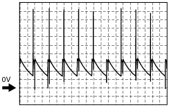
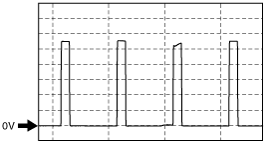
Fuel inject control signal (high)
am3zzw00008136
|
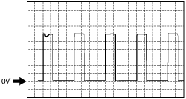
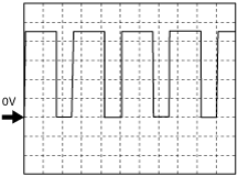
Variable boost control signal
am3zzw00008147
|
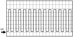
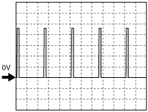
Generator command
am3zzw00008148
|
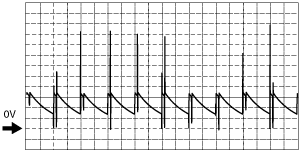
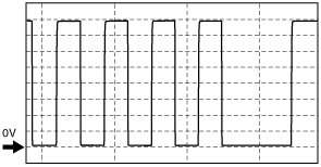
Fuel inject control signal (low)
am3zzw00001038
|
Fuel metering valve control signal
am3zzw00008149
|
EGR valve servo motor control signal
am3zzw00008150
|
CKP sensor signal
am3zzw00008151
|
CMP sensor signal
am3zzw00008152
|
APP sensor signal
Accelerator pedal is released
am3zzw00010054
|
Accelerator pedal is depressed
am3zzw00010055
|
Using the M-MDS (reference)
PID monitor table
|
Item (Definition) |
Unit/ Condition |
Condition/Specification (Reference) |
Inspection item(s) |
PCM terminal |
|||
|---|---|---|---|---|---|---|---|
|
ABS_MSG
(The CAN communication with the ABS HU/CU)
|
Present/
Not Present
|
• The CAN communication with the ABS HU/CU is normal: Present
• The CAN communication with the ABS HU/CU malfunction: Not Present
|
• PCM
• ABS HU/CU
• DSC HU/CU
• CAN
|
—
|
|||
|
ACCS
(A/C relay)
|
On/Off
|
• A/C is operating: On
• A/C is not operating: Off
• Accelerator pedal is depressed: Off
|
• The following PIDs
|
112
|
|||
|
AC_LOWSW
(Cycling switch)
|
On/Off
|
• Refrigerant pressure switch (low) ON: On
• Refrigerant pressure switch (low) OFF: Off
|
• Refrigerant pressure switch (low)
|
303
|
|||
|
AC_REQ
(A/C request signal)
|
On/Off
|
• A/C switch OFF: Off
• A/C switch ON: On
|
• A/C switch
|
—
|
|||
|
ALTF
(Generator field coil control duty signal)
|
%
|
• Switch the ignition to ON: 0 %
• Idle, E/L is operating: Duty value increases.
|
• The following PIDs
• Generator
|
107
|
|||
|
APP
(Accelerator pedal position)
|
%
|
• Accelerator pedal is released: 0 %
• Accelerator pedal is depressed: Approx. 99.6 %
|
• APP sensor
|
310
|
|||
|
ARPMDES
(Target idle speed)
|
RPM
|
• Indicates the target idle speed
|
—
|
—
|
|||
|
BARO
(Barometric pressure)
|
Pa
|
Bar
|
psi
|
• Indicates the atmospheric pressure
|
• PCM
|
—
|
|
|
BOO
(Brake switch)
|
On/Off
|
• Brake pedal is depressed: On
• Brake pedal is released: Off
|
• Brake switch
|
317
|
|||
|
CAB_FLOV
(Air bypass valve first learnt offset value)
|
%
|
• Displays the correction value for the initial learning.
|
—
|
—
|
|||
|
CABVDC
(Air bypass valve duty cycle)
|
%
|
• Switch the ignition to ON: 2.25 %
|
• Air bypass valve
|
248
|
|||
|
CABVP
(Air bypass valve position sensor)
|
%
|
• Switch the ignition to ON: 0.87 %
• Idle: 0.87 % (Note: It operates at the time of a diesel particulate filter regeneration.)
|
• Air bypass valve position sensor
|
233
|
|||
|
COLP
(Refrigerant pressure switch (medium pressure switch))
|
On/Off
|
• Refrigerant pressure switch (medium pressure switch) is 1.39—1.65 MPa {14.2—16.8 kgf/cm2, 202—239 psi} or more: On
• Refrigerant pressure switch (medium pressure switch) is 1.08—1.38 MPa {11.1—14.0 kgf/cm2, 157—200 psi} or less: Off
|
• Refrigerant pressure switch (medium-pressure switch)
|
315
|
|||
|
DIS_ASHFULL
(Distance until diesel particulate filter ash full)
|
Km
|
mile
|
• The distance travelled from which soot is deposited at the acceptable amount for the diesel particulate filter
|
—
|
—
|
||
|
DIST_REGEN
(Distance since last diesel particulate filter regeneration)
|
Km
|
mile
|
• Indicates the distance travelled after diesel particulate filter regeneration.
|
—
|
—
|
||
|
DPF_DIF
(Diesel particulate filter differential pressure sensor)
|
Pa
|
Bar
|
psi
|
• Switch the ignition to ON: 0 kPa {0 kgf/cm2, 0 psi}
• Idle: 0—1 kPa {0—0.010 kgf/cm2, 0—0.145 psi}
|
• Diesel particulate filter differential pressure sensor
|
246
|
|
|
DTCCNT
(DTC count)
|
No unit
|
• Number of DTCs stored
• When a DTC is not stored, “0” is indicated
|
• DTC
|
—
|
|||
|
ECT
(ECT sensor)
|
°C
|
°F
|
• Indicates the engine coolant temperature
|
• ECT sensor
|
230
|
||
|
EGR_TV
(EGR throttle valve position sensor)
|
%
|
• Switch the ignition to ON: 100 %
• Idle: 0—100 %
|
• EGR throttle valve position sensor
|
222
|
|||
|
EGRDC
(EGR valve)
|
%
|
• Switch the ignition to ON: 100 %
• Idle: Approx. 60—70 %
|
• EGR valve
|
228
|
|||
|
EGRTV_FLOV
(EGR throttle valve first learnt offset value)
|
%
|
• Displays the correction value for the initial learning.
|
—
|
—
|
|||
|
EGRV_FLOV
(EGR valve first learnt offset value)
|
%
|
• Displays the correction value for the initial learning.
|
—
|
—
|
|||
|
EGRVP
(EGR valve position sensor)
|
%
|
• Switch the ignition to ON: 0 %
• Idle: Approx. 30—40 %
|
• EGR valve position sensor
|
129
|
|||
|
ENG_SYNC
(Engine speed synchronization state)
|
No/Yes
|
• Actual engine speed can be followed according to the target engine speed: Yes
• Actual engine speed cannot be followed according to the target engine speed: No
|
—
|
—
|
|||
|
EOT
(Engine oil temperature)
|
°C
|
°F
|
• This procedure is not for diagnosis
|
—
|
—
|
||
|
FAN_DUTY
(Fan control duty value)
|
%
|
• Engine coolant temperature is 80 °C {176 °F} or less: 0 %
• Engine coolant temperature is 85 °C {185 °F}: Approx. 20 %
• Engine coolant temperature is 90 °C {194 °F}: Approx. 40 %
|
• Fan control module
|
318
|
|||
|
FL_CAB
(Status of first learning of CAB valve)
|
Not Learnt/Learnt
|
• Indicates the status of first learning
|
—
|
—
|
|||
|
FL_EGRTV
(Status of first learning of Intake throttle valve)
|
Not Learnt/Learnt
|
• Indicates the status of first learning
|
—
|
—
|
|||
|
FL_EGRV
(Status of first learning of EGR valve)
|
Not Learnt/Learnt
|
• Indicates the status of first learning
|
—
|
—
|
|||
|
FP
(Fuel pump)
|
%
|
• Switch the ignition to ON (After a certain period of time from switch the ignition to ON position): Approx. 15 %
• Idle: Approx. 35—40 %
|
• Fuel pump
|
212
|
|||
|
FRP
(Fuel rail pressure)
|
Pa
|
Bar
|
psi
|
• Indicates the fuel rail pressure
|
• Fuel pressure sensor
|
219
|
|
|
FRT
(Fuel temperature sensor)
|
°C
|
°F
|
• Indicates the fuel temperature
|
• Fuel temperature sensor
|
232
|
||
|
FUEL_STRT
(Fuel pressure enable for start)
|
No/Yes
|
• Fuel pressure necessary for starting engine achieved: Yes
• Fuel pressure necessary for starting engine not achieved: No
|
—
|
—
|
|||
|
GPC
(Glow plug relay)
|
On/Off
|
• Glow plug relay is operating: On
• Glow plug relay is not operating: Off
|
• Glow plug relay
|
132
|
|||
|
IAT
(IAT sensor)
|
°C
|
°F
|
• Indicates the intake air temperature
|
• IAT sensor
|
215
|
||
|
IC_MSG
(The CAN communication with the instrument cluster)
|
Present/
Not Present
|
• The CAN communication with the instrument cluster is normal: Present
• The CAN communication with the instrument cluster malfunction: Not Present
|
• CAN
• Instrument cluster
• PCM
|
—
|
|||
|
INGEAR
(In gear)
|
On/Off
|
• Vehicle in gear and clutch is released: ON
• Except above: OFF
|
—
|
—
|
|||
|
LL_CAB
(Status of last learning of air bypass valve)
|
Not Learnt/Learnt
|
• Indicates the status of last learning
|
—
|
—
|
|||
|
MAF
(MAF sensor)
|
g/s
|
• Indicates the MAF
|
• MAF sensor
|
225
|
|||
|
MAP
(MAP sensor)
|
Pa
|
Bar
|
psi
|
• Indicates the MAP
|
• MAP sensor
|
234
|
|
|
MFDES
(Mass fuel desired in milligrams)
|
g
|
• Displays target fuel quantity.
|
—
|
—
|
|||
|
MIL
(Malfunction indicator lamp)
|
On/Off
|
• Idle, MIL illuminate: ON
• Idle, MIL not illuminate: OFF
|
• Perform applicable DTC troubleshooting.
|
—
|
|||
|
MIL_DIS
(Travelled distance since MIL illuminated)
|
Km
|
mile
|
• Indicates the travelled distance since the MIL illuminated
|
• Perform applicable DTC troubleshooting.
|
—
|
||
|
OPSW
(Oil pressure switch)
|
On/Off
|
• Switch the ignition to ON: On
• Idle: Off
|
• Oil pressure switch
|
313
|
|||
|
PPFT
(Pre-particulate filter temperature)
|
°C
|
°F
|
• Indicates the temperature before passing the diesel particulate filter.
|
• Exhaust gas temperature sensor
|
114,
220
|
||
|
RPM
(Engine speed)
|
RPM
|
• Indicates the engine speed
|
• CKP sensor
|
238
|
|||
|
SEC_TPDC
(Secondary throttle position duty cycle)
|
%
|
• Switch the ignition to ON: 0.85 %
• Idle and No load: 0.85 %
• Idle and A/C ON: 1.02 %
|
—
|
—
|
|||
|
ST_EN_RLY
(Stater relay)
|
Disabled/Enabled
|
• Stater relay is operating: Enabled
• Stater relay is not operating: Disabled
|
• Stater relay
|
108
|
|||
|
TIRESIZE
(Tire revolution per mile)
|
No unit
|
• Indicates the tire revolution per a mile
|
—
|
—
|
|||
|
TORQUE
(Net engine torque)
|
Nm
|
• Indicates the net engine torque
|
—
|
—
|
|||
|
TP
(Throttle Position)
|
PT/WOT/CT
|
• Accelerator pedal is released: CT
• Accelerator pedal is depressed but has not been floored: PT
• Accelerator pedal is depressed: WOT
|
• APP sensor
|
310
|
|||
|
VBCV
(VBC solenoid valve)
|
%
|
• Switch the ignition to ON: Approx. 5 %
• Idle: Approx. 65—70 %
• 2,000 rpm and No load: Approx. 55—60 %
|
• VBC solenoid valve
|
104
|
|||
|
VFDES
(Volume fuel desired)
|
mm3
|
• Displays the demand fuel volume.
|
—
|
—
|
|||
|
VPWR
(Battery positive voltage)
|
V
|
• Switch the ignition to ON: B+
• Idle: B+
|
• Battery
• Main relay
|
236,
241
|
|||
|
VSS
(Vehicle speed)
|
KPH
|
MPH
|
• Indicates the vehicle speed
|
• Perform applicable DTC troubleshooting.
|
—
|
||