am3zzn00002249
|
ON-BOARD DIAGNOSTIC SYSTEM FUNCTION [DYNAMIC STABILITY CONTROL (DSC)]
id0402b2182100
Malfunction detection function
Memory function
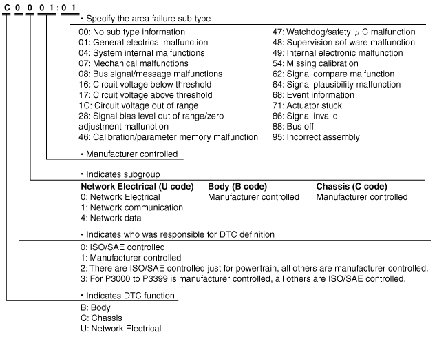
DTC 7-digit code definition
am3zzn00002249
|
Fail-safe function
Fail-safe Function Malfunction Contents
|
Malfunction location |
DTC No. |
Fail-safe function |
|||||||||
|---|---|---|---|---|---|---|---|---|---|---|---|
|
Warning light illumination status |
Control status |
||||||||||
|
Mazda Modular Diagnostic System (M-MDS) display |
ABS warning light |
Brake system warning light (parking brake released) |
DSC indicator light |
DSC OFF light |
ABS control |
EBD control |
TCS Control |
DSC Control |
Brake assist control |
||
|
Brake control |
Engine control |
||||||||||
|
DSC HU/CM internal malfunction (traction control solenoid valve system)
|
C0001:01
|
-
|
-
|
Illuminated
|
-
|
Control disabled
|
Control disabled
|
Control disabled
|
Control disabled
|
Control disabled
|
|
|
C0002:01
|
|||||||||||
|
DSC HU/CM internal malfunction (stability control solenoid valve system)
|
C0003:01
|
-
|
-
|
Illuminated
|
-
|
Control disabled
|
Control disabled
|
Control disabled
|
Control disabled
|
Control disabled
|
|
|
C0004:01
|
|||||||||||
|
DSC HU/CM internal malfunction (LF inlet solenoid)
|
C0010:01
|
Illuminated
|
Illuminated
|
Illuminated
|
-
|
Control disabled
|
Control disabled
|
Control disabled
|
Control disabled
|
Control disabled
|
|
|
DSC HU/CM internal malfunction (LF outlet solenoid)
|
C0011:01
|
||||||||||
|
DSC HU/CM internal malfunction (RF inlet solenoid)
|
C0014:01
|
||||||||||
|
DSC HU/CM internal malfunction (RF outlet solenoid)
|
C0015:01
|
||||||||||
|
DSC HU/CM internal malfunction (LR inlet solenoid)
|
C0018:01
|
||||||||||
|
DSC HU/CM internal malfunction (LR outlet solenoid)
|
C0019:01
|
||||||||||
|
DSC HU/CM internal malfunction (RR inlet solenoid)
|
C001C:01
|
||||||||||
|
DSC HU/CM internal malfunction (RR outlet solenoid)
|
C001D:01
|
||||||||||
|
Pump motor, motor relay
|
C0020:01
|
Illuminated
|
-
|
Illuminated
|
-
|
Control disabled
|
Control enabled
|
Control disabled
|
Control disabled
|
Control disabled
|
|
|
C0020:1C
|
|||||||||||
|
C0020:71
|
|||||||||||
|
ABS sensor rotor
|
C0030:07
|
Illuminated
|
-*1
|
Illuminated
|
-
|
Control disabled
|
Control enabled*2
|
Control disabled
|
Control disabled
|
Control disabled
|
|
|
C0033:07
|
|||||||||||
|
C0036:07
|
|||||||||||
|
C0039:07
|
|||||||||||
|
ABS wheel-speed sensor
|
C0031:01
|
Illuminated
|
-*1
|
Illuminated
|
-
|
Control disabled
|
Control enabled*2
|
Control disabled
|
Control disabled
|
Control disabled
|
|
|
C0034:01
|
|||||||||||
|
C0037:01
|
|||||||||||
|
C003A:01
|
|||||||||||
|
ABS wheel-speed sensor/ABS sensor rotor
|
C0031:07
|
Illuminated
|
-*1
|
Illuminated
|
-
|
Control disabled
|
Control enabled*2
|
Control disabled
|
Control disabled
|
Control disabled
|
|
|
C0034:07
|
|||||||||||
|
C0037:07
|
|||||||||||
|
C003A:07
|
|||||||||||
|
Brake switch
|
C0040:64
|
-
|
-
|
-
|
-
|
Control enabled
|
Control enabled
|
Control enabled
|
Control enabled
|
Control enabled
|
|
|
Brake fluid pressure sensor
|
C0044:01
|
-
|
-
|
illuminated
|
-
|
Control enabled
|
Control enabled
|
Control disabled
|
Control disabled
|
Control disabled
|
|
|
C0044:28
|
|||||||||||
|
C0044:54
|
|||||||||||
|
C0044:64
|
|||||||||||
|
Steering angle sensor
|
C0051:28
|
-
|
-
|
illuminated
|
-
|
Control enabled
|
Control enabled
|
Control enabled
|
Control disabled
|
Control disabled
|
Control enabled
|
|
Combined sensor system*3
|
C0061:01
|
-
|
-
|
illuminated
|
-
|
Control enabled
|
Control enabled
|
Control enabled
|
Control disabled
|
Control disabled
|
Control enabled
|
|
C0061:28
|
|||||||||||
|
C0061:64
|
|||||||||||
|
C0063:01
|
|||||||||||
|
C0063:28
|
|||||||||||
|
C0063:64
|
|||||||||||
|
C006A:01
|
|||||||||||
|
C006A:16
|
|||||||||||
|
C006A:17
|
|||||||||||
|
C006A:95
|
|||||||||||
|
SAS control module system*4
|
C0061:28
|
-
|
-
|
illuminated
|
-
|
Control enabled
|
Control enabled
|
Control enabled
|
Control disabled
|
Control disabled
|
Control enabled
|
|
C0061:64
|
|||||||||||
|
C0063:28
|
|||||||||||
|
C0063:64
|
|||||||||||
|
DSC HU/CM system (unperformed initialization procedure)
|
C0061:54
|
-
|
-
|
illuminated
|
-
|
Control enabled
|
Control enabled
|
Control enabled
|
Control disabled
|
Control disabled
|
Control enabled
|
|
C0063:54
|
|||||||||||
|
Combined sensor (internal malfunction)*3
|
C006A:04
|
-
|
-
|
illuminated
|
-
|
Control enabled
|
Control enabled
|
Control enabled
|
Control disabled
|
Control disabled
|
Control enabled
|
|
C006A:47
|
|||||||||||
|
TCS/DSC control system
|
C006B:00
|
-
|
-
|
illuminated
|
-
|
Control enabled
|
Control enabled
|
Control enabled
|
Control disabled
|
Control disabled
|
Control enabled
|
|
C0072:68
|
-
|
Control enabled
|
|||||||||
|
DSC HU/CM (internal malfunction)
|
B10DF:46
|
-
|
-
|
illuminated
|
-
|
Control enabled
|
Control enabled
|
Control disabled
|
Control disabled
|
Control disabled
|
|
|
C0082:47
|
illuminated
|
illuminated
|
illuminated
|
-
|
Control disabled
|
Control disabled
|
Control disabled
|
Control disabled
|
Control disabled
|
||
|
C0082:48
|
|||||||||||
|
C0082:49
|
|||||||||||
|
C1B14:01*4
|
-
|
-
|
illuminated
|
-
|
Control enabled
|
Control enabled
|
Control enabled
|
Control disabled
|
Control disabled
|
Control enabled
|
|
|
U2007:46
|
illuminated
|
-
|
illuminated
|
-
|
Control disabled
|
Control enabled
|
Control disabled
|
Control disabled
|
Control disabled
|
||
|
DSC OFF switch
|
C1109:64
|
-
|
-
|
illuminated
|
-
|
Control enabled
|
Control enabled
|
Control enabled
|
Control enabled
|
Control enabled
|
|
|
CAN line
|
U0001:88
|
illuminated
|
-
|
illuminated
|
-
|
Control enabled
|
Control enabled
|
Control enabled
|
Control disabled
|
Control disabled
|
Control enabled
|
|
U0100:00
|
-
|
-
|
illuminated
|
-
|
Control enabled
|
Control enabled
|
Control enabled
|
Control disabled
|
Control disabled
|
Control enabled
|
|
|
U0101:00*5
|
-
|
-
|
illuminated
|
-
|
Control enabled
|
Control enabled
|
Control enabled
|
Control disabled
|
Control disabled
|
Control enabled
|
|
|
U0140:00
|
-
|
-
|
illuminated
|
-
|
Control enabled
|
Control enabled
|
Control enabled
|
Control disabled
|
Control disabled
|
Control enabled
|
|
|
U0155:00
|
illuminated
|
-
|
illuminated
|
-
|
Control enabled
|
Control enabled
|
Control enabled
|
Control enabled
|
Control enabled
|
||
|
Combined sensor system (CAN2 line malfunction)*3
|
U0125:00
|
-
|
-
|
illuminated
|
-
|
Control enabled
|
Control enabled
|
Control enabled
|
Control disabled
|
Control disabled
|
Control enabled
|
|
U0125:88
|
|||||||||||
|
SAS control module system (CAN2 line malfunction)*4
|
U0151:00
|
-
|
-
|
illuminated
|
-
|
Control enabled
|
Control enabled
|
Control enabled
|
Control disabled
|
Control disabled
|
Control enabled
|
|
Abnormal message from PCM
|
U0401:00
|
-
|
-
|
illuminated
|
-
|
Control enabled
|
Control enabled
|
Control enabled
|
Control disabled
|
Control disabled
|
Control enabled
|
|
Abnormal message from PCM (MTX, ATX (FN4A-EL))
Abnormal message from TCM (ATX (FS5A-EL))
|
U0402:00
|
||||||||||
|
Abnormal message from BCM
|
U0422:00
|
-
|
-
|
illuminated
|
-
|
Control enabled
|
Control enabled
|
Control enabled
|
Control disabled
|
Control disabled
|
Control enabled
|
|
U0428:62
|
illuminated
|
-
|
illuminated
|
||||||||
|
U0428:64
|
|||||||||||
|
DSC HU/CM configuration
|
U2100:00
|
illuminated
|
-
|
illuminated
|
-
|
Control disabled
|
Control enabled
|
Control disabled
|
Control disabled
|
Control disabled
|
|
|
U2101:00
|
|||||||||||
|
Abnormal message from SAS control module*4
|
U0452:86
|
-
|
-
|
illuminated
|
-
|
Control enabled
|
Control enabled
|
Control enabled
|
Control disabled
|
Control disabled
|
Control enabled
|
|
Power supply system
|
U3003:08
|
-
|
-
|
-
|
-
|
Control enabled
|
Control enabled
|
Control enabled
|
Control enabled
|
Control enabled
|
Control enabled
|
|
U3003:16
|
Illuminated
|
-*6
|
illuminated
|
-
|
Control disabled
|
Control enabled*6
|
Control disabled
|
Control disabled
|
Control disabled
|
||
|
Illuminated*7
|
Control disabled*7
|
||||||||||
|
U3003:17
|
Illuminated
|
Illuminated
|
Control disabled
|
||||||||