 |
am3zzw00005765
POWER BRAKE UNIT REMOVAL/INSTALLATION (R.H.D.) [LF, L5]
id0411008038i2
1. Remove the master cylinder. (See MASTER CYLINDER REMOVAL/INSTALLATION [ZY, Z6, LF, L5, MZ-CD 1.6 (Y6), MZR-CD 2.2].)
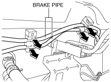
2. Detach the brake pipes from the brake pipe brackets.
am3zzw00005765
|
3. Remove the coolant reserve tank from the vehicle and move the coolant reserve tank in the direction of the arrow.
am3zzw00005769
|
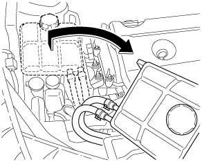
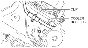
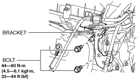
4. For LF vehicles, perform the following procedure:
am3zzw00008224
|
am3zzw00008800
|
am3zzw00005772
|
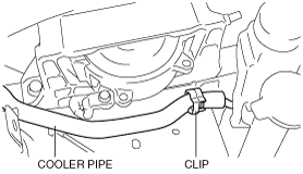
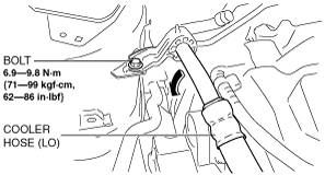
5. For L5 vehicles, perform the following procedure:
am3zzw00008225
|
am3zzw00007635
|
am3zzw00007636
|
6. Remove the dashboard under cover. (If equipped) (See DASHBOARD UNDER COVER REMOVAL/INSTALLATION.)
7. Disconnect the steering shaft from the steering gear and linkage. (See STEERING WHEEL AND COLUMN REMOVAL/INSTALLATION [WITHOUT ADVANCED KEYLESS ENTRY AND PUSH BUTTON START SYSTEM].) (See STEERING WHEEL AND COLUMN REMOVAL/INSTALLATION [WITH ADVANCED KEYLESS ENTRY AND PUSH BUTTON START SYSTEM].)
8. Remove in the order indicated in the table.
9. Remove the brake switch. (See BRAKE PEDAL REMOVAL/INSTALLATION [R.H.D.].)
10. Install in the reverse order of removal.
11. After installation, inspect the brake pedal. (See BRAKE PEDAL INSPECTION.)
am3zzw00006463
|
|
1
|
Vacuum hose
(See Vacuum Hose Removal Note.)
|
|
2
|
Joint pin
|
|
3
|
Nut
|
|
4
|
Power brake unit
|
|
5
|
Gasket
|
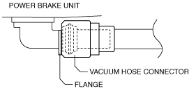
Vacuum Hose Removal Note
1. Disconnect the vacuum hose connector from the power brake unit while pressing the tabs of the vacuum hose connector.
am3zzw00006074
|
Vacuum Hose Installation Note
1. Insert the vacuum hose connector to the power brake unit.
2. Verify that the vacuum hose is inserted so that the connector contacts the power brake unit flange.
am3uuw00001800
|