DYNAMIC STABILITY CONTROL (DSC) OUTLINE
id041500100300
-
Note
-
• Vehicles with combined sensor: Applied VIN (assumed)
European (L.H.D. U.K.) specs.
-
• JMZ BL12F60# 100001—181415
• JMZ BL12F70# 100001—181415
• JMZ BL12Y20# 100001—181415
• JMZ BL12Z20# 100001—181415
• JMZ BL12Z50# 100001—181415
• JMZ BL14F60# 100001—181415
• JMZ BL14F70# 100001—181415
• JMZ BL14Y20# 100001—181415
• JMZ BL14Z20# 100001—181415
• JMZ BL14Z50# 100001—181415
• JMZ BLA2A60# 100001—181415
• JMZ BLA2C60# 100001—181415
• JMZ BLA2F70# 100001—181415
• JMZ BLA2G60# 100001—181415
• JMZ BLA2Y60# 100001—181415
• JMZ BLA2Z20# 100001—181415
• JMZ BLA2Z50# 100001—181415
• JMZ BLA4360# 100001—181415
• JMZ BLA4A60# 100001—181415
• JMZ BLA4C60# 100001—181415
• JMZ BLA4F70# 100001—181415
• JMZ BLA4G60# 100001—181415
• JMZ BLA4Y60# 100001—181415
• JMZ BLA4Z20# 100001—181415
• JMZ BLA4Z50# 100001—181415
Australian specs.
-
• JM0 BL103100 100001—225632
• JM0 BL10C100 100001—225632
• JM0 BL10F100 100001—225632
• JM0 BL10L100 100001—225632
General (R.H.D.) specs.
-
• JM6 BL1031*0 100001—225632
• JM6 BL1051*0 100001—225632
• JM6 BL10F1*0 100001—225632
• JM6 BL10L1*0 100001—225632
• JM6 BL10Z1*0 100001—225632
General (L.H.D.) specs., Arab Gulf Cooperation Council, China
-
• JM7 BL04F**# 100001—225632
• JM7 BL04Z**# 100001—225632
• JM7 BL12F**# 100001—225632
• JM7 BL12Z**# 100001—225632
• JM7 BL14F**# 100001—225632
• JM7 BL14Z**# 100001—225632
• JM7 BL22F**# 100001—225632
• JM7 BL22Z**# 100001—225632
• JM7 BL24F**# 100001—225632
• JM7 BL24Z**# 100001—225632
• Vehicles without combined sensor: Applied VIN (assumed)
European (L.H.D. U.K.) specs.
-
• JMZ BL12F60# 181416—
• JMZ BL12F70# 181416—
• JMZ BL12Y20# 181416—
• JMZ BL12Z20# 181416—
• JMZ BL12Z50# 181416—
• JMZ BL14F60# 181416—
• JMZ BL14F70# 181416—
• JMZ BL14Y20# 181416—
• JMZ BL14Z20# 181416—
• JMZ BL14Z50# 181416—
• JMZ BLA2A60# 181416—
• JMZ BLA2C60# 181416—
• JMZ BLA2F70# 181416—
• JMZ BLA2G60# 181416—
• JMZ BLA2Y60# 181416—
• JMZ BLA2Z20# 181416—
• JMZ BLA2Z50# 181416—
• JMZ BLA4360# 181416—
• JMZ BLA4A60# 181416—
• JMZ BLA4C60# 181416—
• JMZ BLA4F70# 181416—
• JMZ BLA4G60# 181416—
• JMZ BLA4Y60# 181416—
• JMZ BLA4Z20# 181416—
• JMZ BLA4Z50# 181416—
Australian specs.
-
• JM0 BL103100 225633—
• JM0 BL10C100 225633—
• JM0 BL10F100 225633—
• JM0 BL10L100 225633—
General (R.H.D.) specs.
-
• JM6 BL1031*0 225633—
• JM6 BL1051*0 225633—
• JM6 BL10F1*0 225633—
• JM6 BL10L1*0 225633—
• JM6 BL10Z1*0 225633—
General (L.H.D.) specs., Arab Gulf Cooperation Council, China
-
• JM7 BL04F**# 225633—
• JM7 BL04Z**# 225633—
• JM7 BL12F**# 225633—
• JM7 BL12Z**# 225633—
• JM7 BL14F**# 225633—
• JM7 BL14Z**# 225633—
• JM7 BL22F**# 225633—
• JM7 BL22Z**# 225633—
• JM7 BL24F**# 225633—
• JM7 BL24Z**# 225633—
• The DSC HU/CM, integrating both the hydraulic unit (HU) and control module (CM), has been adopted, resulting in a size and weight reduction.
• An enhanced malfunction diagnosis system, used with the Mazda Modular Diagnostic System (M-MDS), improving serviceability.
• A combined sensor, integrating both the yaw rate sensor and lateral-G sensor, has been adopted, improving serviceability. (Vehicles with combined sensor)
• The specialized controller area network (CAN) system (CAN2 line) has been adopted for use between the combined sensor and DSC HU/CM, improving serviceability and reliability. (Vehicles with combined sensor)
• Serviceability improved by the automatic configuration function.
• Electrical brake assist control has been adopted, improving safety.
• Receives the lateral-G and yaw rate signals between the sophisticated air bag sensor (SAS) control module and the DSC HU/CM via controller area network (CAN) lines instead of the conventional combined sensor. (Vehicles without combined sensor)
DSC Operation Outline
• The ABS prevents wheel lock-up during braking. The TCS detects drive wheel spin due to the accelerator pedal being pressed too hard or similar causes and controls engine speed to suppress wheel spin. With these systems, safety is assured when driving or stopping.
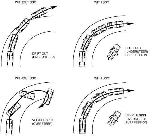
• Additionally, sudden changes in vehicle attitude, due to evasive steering or road conditions, are controlled by the DSC. The DSC suppresses vehicle sideslip when driving due to vehicle spin (oversteer) or drift-out (understeer) by controlling braking and engine speed. At this time, the DSC indicator light illuminates to alert the driver that the DSC is operating due to a dangerous situation. As a result, the driver can calmly react and is provided leeway for the next maneuver, resulting in safe driving conditions.
• In this way the combination of DSC + ABS + TCS ensures driving, stopping and turning safety in all aspects.
Results Of DSC Operation
-
Caution
-
Vehicles with combined sensor
• While the DSC is a steering safety system, it does not improve normal steering function. Therefore, always drive carefully, even if the vehicle has DSC, and do not overestimate the DSC capability.
• If the initialization procedures for the combined and brake fluid pressure sensors are not performed correctly, an incorrectly determined initial point may cause a discrepancy between the actual driving conditions of the vehicle and the signals from the sensors, resulting in improper DSC operation. Therefore, after replacing or removing the following parts, make sure to perform the DSC HU/CM initialization procedures of the sensors with the vehicle stopped on a level ground to insure proper DSC operation. For the initialization procedures of the sensors, refer to the Workshop Manual.
-
― DSC HU/CM
― Combined sensor
• The DSC and ABS will not operate normally under the following conditions:
-
― With tires that are not of the specified size, manufacturer or tread pattern, or not inflated according to specification
― With tires that have significant comparative wear variation
― With tire chains
― With an emergency spare tire
Vehicles without combined sensor
• While the DSC is a steering safety system, it does not improve normal steering function. Therefore, always drive carefully, even if the vehicle has DSC, and do not overestimate the DSC capability.
• If the initialization procedures for the brake fluid pressure and low-G sensors are not performed correctly, an incorrectly determined initial point may cause a discrepancy between the actual driving conditions of the vehicle and the signals from the sensors, resulting in improper DSC operation. Therefore, after replacing or removing the following parts, make sure to perform the DSC HU/CM initialization procedures of the sensors with the vehicle stopped on a level ground to insure proper DSC operation. For the initialization procedures of the sensors, refer to the Workshop Manual.
-
― DSC HU/CM
• The DSC and ABS will not operate normally under the following conditions:
-
― With tires that are not of the specified size, manufacturer or tread pattern, or not inflated according to specification
― With tires that have significant comparative wear variation
― With tire chains
― With an emergency spare tire