 |
am3zzw00007833
PCM OUTLINE [FN4A-EL]
id051701286300
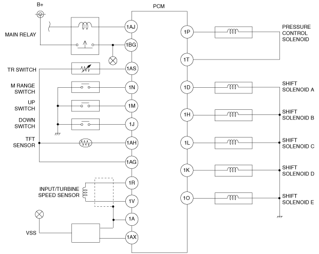
Wiring Diagram
am3zzw00007833
|
Function
|
Item |
Outline |
|---|---|
|
Automatic shift control
|
• The PCM selects the most suitable automatic shift diagram on the results of the driving range and driving mode judgements.
• Based on the automatic shift diagram, the PCM controls the output devices to perform shifting according to the vehicle speed and the accelerator pedal depressing amount.
|
|
Manual shift control
|
• In M range, the PCM selects the manual shift diagram.
• Based on the manual shift diagram, the PCM controls the output devices to perform shifting according to the vehicle speed and the driver’s up-shift/down-shift operation.
|
|
Slope mode control
|
• Climbing is determined based on the engine torque and the vehicle acceleration, and the shift gear is controlled to realize smooth vehicle driving.
|
|
TCC control
|
• The PCM selects the TCC diagram based on the shift control results.
• Based on the TCC diagram, the PCM controls the output devices to engage the TCC according to the vehicle speed and the accelerator pedal depressing amount.
• Smooth TCC control, which engages the TCC gradually, has been adopted to reduce the shock when the TCC engages.
|
|
Slip control
|
• When the accelerator pedal is fully released for deceleration, power transfer efficiency has been improved through a slip control on the torque converter set under a specified range of conditions. As a result, fuel economy, emission performance, and ride comfort have been improved.
|
|
Line pressure control
|
• The PCM adjusts the pressure control solenoid pressure by driving the pressure control solenoid according to the accelerator pedal depressing amount, vehicle speed, ATF temperature and gear position.
• As a result, the line pressure is controlled very accurately and closely.
|
|
Direct electric shift control
|
• The PCM determines the optimum clutch engagement pressure and drives the solenoid valves based on input signals in accordance with the vehicle driving conditions including the engine torque.
• By driving the solenoid valves, and performing the electronic control of the clutch engagement pressure directly through the PCM, minute hydraulic control, which could not be obtained by the clutch engagement pressure control with the accumulator, is obtained.
|
|
Feedback control
|
• When shifting, real-time feedback correction of the clutch engagement pressure is operated by the solenoid valves so that the speed change of the turbine shaft (change of the turbine rotating speed) matches the predetermined target value.
|
|
Engine-transaxle total control
|
• When shifting, engine output torque is reduced temporarily and the clutch is engaged smoothly by engine ignition timing retard control to reduce the fluctuation of the output shaft torque during shifting.
|
|
On-board diagnostic system
|
• The PCM detects malfunctions in the transaxle while driving.
• Minimum vehicle drivability is obtained by changing the signals that are determined to be malfunctions by the malfunction detection function to the preset values, and limiting PCM control.
|
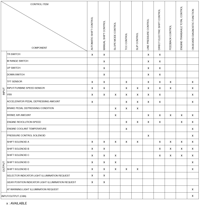
Relation Chart
am3zzn00002506
|