|
am3uuw00004705
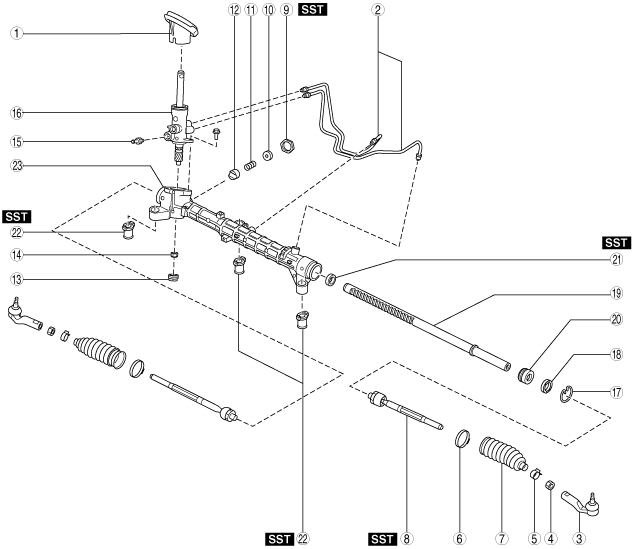
STEERING GEAR AND LINKAGE DISASSEMBLY
id061400801000
1. Disassemble in the order indicated in the table.
L.H.D.
am3uuw00004705
|
|
1
|
Floor seal
|
|
2
|
Oil pipe
|
|
3
|
Tie-rod end
(See Tie-rod End Disassembly Note.)
|
|
4
|
Locknut
|
|
5
|
Boot clamp
|
|
6
|
Boot band
|
|
7
|
Boot
|
|
8
|
Tie rod
(See Tie Rod Disassembly Note.)
|
|
9
|
Locknut (on adjusting cover)
|
|
10
|
Adjusting cover
|
|
11
|
Yoke spring
|
|
12
|
Support yoke
|
|
13
|
Housing cover
|
|
14
|
Locknut (on pinion shaft)
|
|
15
|
Return pipe
|
|
16
|
Pinion shaft and valve housing component
|
|
17
|
Clip
|
|
18
|
Stopper
|
|
19
|
Steering rack
|
|
20
|
Rack bushing
|
|
21
|
Oil seal
(See Oil Seal Disassembly Note.)
|
|
22
|
Mounting rubber
|
|
23
|
Gear housing
|
R.H.D.
am3zzw00005177
|
|
1
|
Floor seal
|
|
2
|
Oil pipe
|
|
3
|
Tie-rod end
(See Tie-rod End Disassembly Note.)
|
|
4
|
Locknut
|
|
5
|
Boot clamp
|
|
6
|
Boot band
|
|
7
|
Boot
|
|
8
|
Tie rod
(See Tie Rod Disassembly Note.)
|
|
9
|
Locknut (on adjusting cover)
|
|
10
|
Adjusting cover
|
|
11
|
Yoke spring
|
|
12
|
Support yoke
|
|
13
|
Housing cover
|
|
14
|
Locknut (on pinion shaft)
|
|
15
|
Return pipe
|
|
16
|
Pinion shaft and valve housing component
|
|
17
|
Clip
|
|
18
|
Stopper
|
|
19
|
Steering rack
|
|
20
|
Rack bushing
|
|
21
|
Oil seal
(See Oil Seal Disassembly Note.)
|
|
22
|
Mounting rubber
|
|
23
|
Gear housing
|
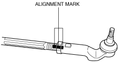
Tie-rod End Disassembly Note
1. Place alignment marks as shown in the figure for proper installation.
am3uuw00003165
|
2. Remove the tie-rod end.
Boot Band (Crimp Type) Disassembly Note
1. Insert a flathead screw driver into the boot band as shown in the figure, then press the caulked area outward to remove the boot band.
am3zzw00009651
|
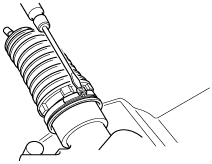
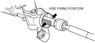
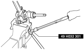
Tie Rod Disassembly Note
1. Protect the steering rack tooth surface using a clean cloth and secure it using a vise.
am3uuw00006910
|
2. Remove the tie rod using the SST.
am3uuw00003167
|
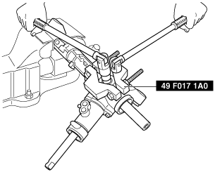
Locknut (on Adjusting Cover), Adjusting Cover Disassembly Note
1. Remove the locknut using the SST.
am3uuw00003168
|
2. Remove the adjusting cover.
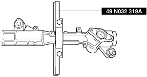
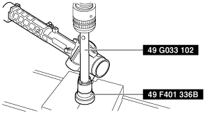
Oil Seal Disassembly Note
1. Install the SST (49 N032 319A) to the gear housing as shown in the figure.
am3uuw00004677
|
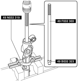
2. Insert the SSTs (49 F032 303, 49 B032 323) into the valve housing side.
3. Remove the oil seal using the SSTs and a press.
am3uuw00003170
|
Mounting Rubber Disassembly Note
1. Remove the mounting rubber from the gear housing using the SSTs and a press.
am3uuw00003171
|