 |
acxuun00000222
ON-BOARD DIAGNOSTIC FUNCTION
id070200100300
Malfunction detection function
Fail-safe function
Fail-safe Function Table
|
Part where malfunction is determined |
Malfunction determined when IG SW at ON |
Malfunction already exists when IG SW turned to ON |
|---|---|---|
|
Cabin temperature sensor
|
Cabin temperature sensor input value is fixed at the value right before the malfunction.
|
Cabin temperature sensor input value is fixed at 25 °C {77 °F}.
|
|
Evaporator temperature sensor
|
A/C output OFF is controlled when the evaporator temperature sensor input value is at 0 °C {32 °F}.
|
←
|
|
Heater core temperature sensor
|
Heater core temperature sensor input value is fixed at 50 °C {122 °F}.
|
←
|
|
Solar radiation sensor
|
The solar radiation sensor input value is fixed at the value directly before the malfunction only when the valve is 1,450 W/m2 or more.
|
Solar radiation sensor value is fixed at 0 W/m2.
|
|
Engine coolant temperature sensor
|
Engine coolant temperature sensor input value is fixed at 95 °C {203 °F}.
|
←
|
|
Refrigerant pressure sensor
|
Refrigerant pressure sensor input value is fixed at 1.5 MPa {15 kgf/cm2, 218 psi}.
|
←
|
|
Air mix actuator
(potentiometer)
|
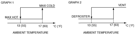
Air mix actuator drive signal is stopped right when the malfunction is determined.
However, it is fixed at MAX COLD when the manually set temperature is at 15 and fixed at MAX HOT when the manually set temperature is at 29.
|
Control based on ambient temperature.
(See Graph 1.)
However, it is fixed at MAX COLD when the manually set temperature is at 15 and fixed at MAX HOT when the manually set temperature is at 29.
|
|
Airflow mode actuator
(potentiometer)
|
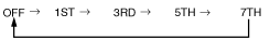
Airflow mode actuator drive signal is stopped right when the malfunction is determined.
• However, change the operation to VENT or DEF when the manual operation selected to VENT or DEF.
|
Control based on ambient temperature.
(See Graph 2.)
• However, change the operation to VENT or DEF when the manual operation selected to VENT or DEF.
|
|
Air mix actuator
(motor lock)
|
Air mix actuator drive signal is stopped right when the malfunction is determined.
|
The climate control unit outputs air mix actuator drive voltage for 20 s. If the potentiometer does not reach the target voltage, a malfunction is determined and the motor is stopped.
|
|
Airflow mode actuator
(motor lock)
|
Airflow mode actuator drive signal is stopped right when the malfunction is determined.
|
The climate control unit outputs airflow mode actuator drive voltage for 9 s. If the potentiometer does not reach the target voltage, a malfunction is determined and the motor is stopped.
|
|
Water heater unit
|
Stops the water heater system operation.
|
←
|
acxuun00000222
|
Memory Function
Display Function
am3uun00001014
|
DTC table (climate control system)
|
DTC |
Malfunction location |
Detected condition |
Memory function |
|---|---|---|---|
|
B1081:71
|
• Driver-side air mix actuator (L.H.D.)
• Passenger-side air mix actuator (R.H.D.)
|
Motor lock
|
X
|
|
B1082:71
|
• Driver-side air mix actuator (R.H.D.)
• Passenger-side air mix actuator (L.H.D.)
|
Motor lock
|
X
|
|
B1086:71
|
Airflow mode actuator
|
Motor lock
|
X
|
|
B1A61:11
|
Cabin temperature sensor
|
Circuit short to ground
|
X
|
|
B1A61:13
|
Circuit open
|
X
|
|
|
B1A63:12
|
Solar radiation sensor (RH)
|
Circuit shot to power supply
|
—
|
|
B1A63:13
|
Circuit open
|
—
|
|
|
B1A64:12
|
Solar radiation sensor (LH)
|
Circuit shot to power supply
|
—
|
|
B1A64:13
|
Circuit open
|
—
|
|
|
B1B71:11
|
Evaporator temperature sensor
|
Circuit short to ground
|
X
|
|
B1B71:13
|
Circuit open
|
X
|
|
|
B1C1A:11
|
• Driver-side air mix actuator (potentiometer) (L.H.D.)
• Passenger-side air mix actuator (potentiometer) (R.H.D.)
|
Circuit short to ground
|
X
|
|
B1C1A:13
|
Circuit open
|
X
|
|
|
B1C1B:11
|
• Passenger-side air mix actuator (potentiometer) (L.H.D.)
• Driver-side air mix actuator (potentiometer) (R.H.D.)
|
Circuit short to ground
|
X
|
|
B1C1B:13
|
Circuit open
|
X
|
|
|
B1C1C:11
|
Airflow mode actuator (potentiometer)
|
Circuit short to ground
|
X
|
|
B1C1C:13
|
Circuit open
|
X
|
|
|
B1D22:11
|
Heater core temperature sensor
|
Circuit short to ground
|
X
|
|
B1D22:13
|
Circuit open
|
X
|
|
|
P0530:12
|
Refrigerant pressure sensor
|
Circuit short to power supply
|
X
|
|
P0530:13
|
Circuit open
|
X
|
|
|
U0010:88
|
CAN communication system
|
Bus off
|
X
|
|
U0155:00
|
Lost communication with instrument cluster
|
No sub type information
|
X
|
|
U0166:00
|
Lost communication with water heater unit
|
No sub type information
|
X
|
|
U0156:00
|
Lost communication with information display
|
No sub type information
|
X
|
|
U0423:68
|
Invalid date received from Instrument cluster
|
Event information
|
X
|
|
U0425:68
|
Invalid date received from water heater unit
|
Event information
|
X
|
|
U3003:16
|
Climate control unit power supply voltage (B+)
|
Power supply voltage decreases (9.7 V or less)
|
X
|
|
U3003:17
|
Climate control unit power supply voltage (B+, IG2, TNS)
|
Power supply voltage increases (16.4 V or more (B+))
(16.8 V or more (IG2, TNS))
|
X
|
DTC table (water heater system)
|
DTC |
System malfunction location |
Memory function |
|---|---|---|
|
B1004
|
Glow plug malfunction: short to battery or transistor failure
|
X
|
|
B1005
|
Fuel pump (water heater system) malfunction: short to battery or transistor failure
|
X
|
|
B1006
|
Fuel level to low to start the heater
|
X
|
|
B1008
|
Blower fan malfunction: short to battery
|
X
|
|
B1317
|
Input voltage high
|
X
|
|
B1318
|
Input voltage low
|
X
|
|
B1342
|
Malfunction in water heater unit
|
X
|
|
B2207
|
Water heater unit ROM checksum error
|
X
|
|
B2449
|
Glow plug circuit short to ground
|
X
|
|
B2450
|
Glow plug circuit open
|
X
|
|
B2451
|
Fuel pump (water heater system) circuit short to ground
|
X
|
|
B2452
|
Fuel pump (water heater system) circuit open
|
X
|
|
B2453
|
Blower fan circuit short to ground
|
X
|
|
B2454
|
Blower fan circuit open
|
X
|
|
B2455
|
Blower fan out of range (electromotive force not present)
|
X
|
|
B2456
|
Coolant sensor short
|
X
|
|
B2457
|
Coolant sensor interrupted
|
X
|
|
B2458
|
Overheat sensor short
|
X
|
|
B2459
|
Overheat sensor interrupted
|
X
|
|
B2460
|
Flame sensor short
|
X
|
|
B2461
|
Flame sensor interrupted
|
X
|
|
B2462
|
• Flame off from max. power
• Flame off from min. power
|
X
|
|
B2463
|
Overheat
|
X
|
|
B2464
|
Start time exceeded
|
X
|
|
B2465
|
Start counter overrun/system locked
|
X
|
|
B2466
|
Overheat counter overrun/system locked
|
X
|
|
B2467
|
Water heater unit cool down time exceeded
|
X
|
|
U1900
|
CAN Communication Bus Fault - Receive Error
|
X
|
|
U2516
|
CAN bus off - Transmit Error
|
X
|
PID/data Monitor Function
PID/data monitor table (climate control system)
|
PID name (definition) |
Input part |
Unit/Condition |
|---|---|---|
|
AC_PRES
|
Refrigerant pressure sensor
|
Pa
|
|
CABIN_TEMP
|
Cabin temperature sensor
|
°C
|
|
EVAP_TEMP
|
Evaporator temperature sensor
|
°C
|
|
HCT
|
Heater core temperature sensor
|
°C
|
|
SOLAR_SSR_L
|
Solar radiation sensor (LH)
|
W
|
|
SOLAR_SSR_R
|
Solar radiation sensor (RH)
|
W
|
PID/data monitor table (water heater system)
|
PID Name (Definition) |
Condition/Specification (Reference) |
Unit/Condition |
|---|---|---|
|
CCNTFFH
(Continuous Codes)
|
• DTC is detected: 1—255
• DTC is not detected: 0
|
—
|
|
FAN
(Fan Control)
|
• Blower fan is not operating: 0%
• Blower fan is operating: 0-100%
|
On/Off
|
|
FUEL_PMP
(Fuel pump)
|
• Fuel pump (water heater unit) is not operating: Off
• Fuel pump (water heater unit) is operating: On
|
On/Off
|
|
GLOW
(Glow plug)
|
• Glow plug is not operating: Off
• Glow plug is operating: On
|
On/Off
|
|
HEATER
(Heater Status)
|
• Water heater unit is not operating: Off
• Water heater unit is operating: On
|
On/Off
|
|
PREFILL
(Water heater unit Lock/Unlock Status After Prefilling)
|
• Water heater unit is not operating: Lock
• Water heater unit is operating: Unlock
|
Lock/Unlock
|
|
VOLT_MDL
(Water heater unit Voltage)
|
• Under any condition: B+
|
V
|
Active Command Modes Function
Active command modes table (climate control system)
|
Command name |
Output part |
Operation |
Operating condition |
|---|---|---|---|
|
BLOWER
|
Blower Motor
|
On/Off
|
Switch the Ignition to ON
|
|
DISPLAY
|
Information display
|
||
|
MODE_ACT
|
Airflow mode actuator
|
||
|
MIX_ACT
|
Air mix actuator
|
||
|
REC/FRESH
|
REC switch
|
Active command modes table (water heater system)
|
Command name (Definition) |
Operation |
Condition/Specification (Reference) |
|---|---|---|
|
FAN
(Fan Control)
|
On/Off
|
• Blower fan is not operating: 0%
• Blower fan is operating: 0-100%
|
|
FUEL_PMP
(Fuel pump)
|
On/Off
|
• Fuel pump (water heater unit) is not operating: Off
• Fuel pump (water heater unit) is operating: On
|
|
GLOW
(Glow plug)
|
On/Off
|
• Glow plug is not operating: Off
• Glow plug is operating: On
|
|
HEATER
(Heater Status)
|
On/Off
|
• Water heater unit is not operating: Off
• Water heater unit is operating: On
|
A/C Operation Check Mode
|
Mazda Modular Diagnostic System (M-MDS) display |
Target part |
Operation condition |
|---|---|---|
|
Illumination of All Indicator lights
|
Climate control unit
|
All A/C indicator lights illuminated
|
|
Blower Motor Speed
|
Blower motor
|
 |
|
Air Mix Actuator
|
Air mix door
|
 |
|
Air Flow Mode Actuator
|
Airflow mode door
|
 |
|
Air Intake Actuator / Air Conditioning Compressor
|
Air intake door
A/C compressor
|
FRESH Û REC
ON Û OFF
|
