 |
am3zzn00002877
A/C UNIT CONSTRUCTION/OPERATION
id071100100400
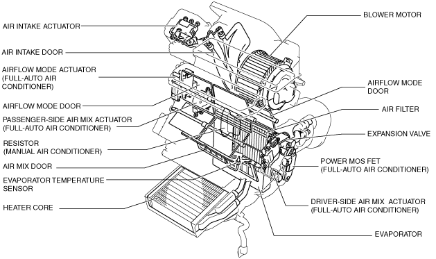
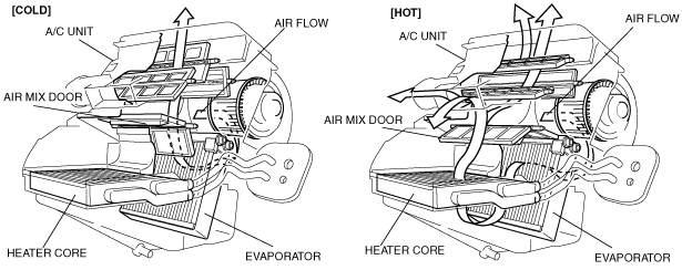
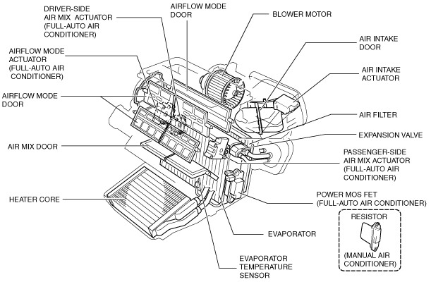
Construction
L.H.D.
am3zzn00002877
|
R.H.D.
am3zzn00002878
|
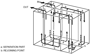
Evaporator
am3zzn00002281
|
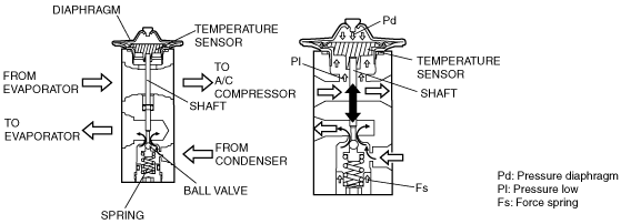
Expansion valve
acxuun00000157
|
Operation
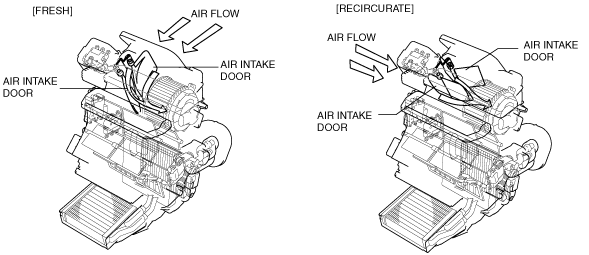
Air Intake Door Operation
L.H.D.
am3uun00000790
|
R.H.D.
am3zzn00002282
|
Air Mix Door Operation
L.H.D.
am3uun00000791
|
R.H.D.
am3zzn00002283
|
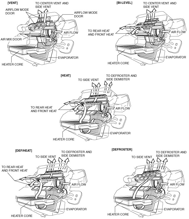
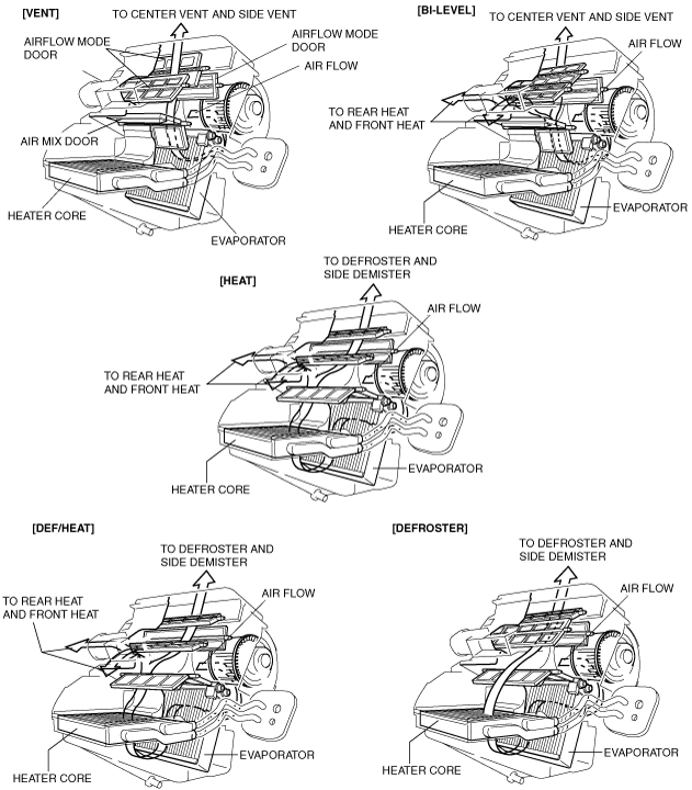
Airflow Mode Door Operation
L.H.D.
am3uun00000792
|
R.H.D.
am3zzn00002844
|
L.H.D.
|
Airflow mode |
Side vent |
Airflow volume ratio (%) (Approx. quantity) |
||||||||||||||
|---|---|---|---|---|---|---|---|---|---|---|---|---|---|---|---|---|
|
VENT |
HEAT |
DEFROSTER |
||||||||||||||
|
Driver side |
Passenger side |
Total |
Front |
Rear |
Total |
Driver side |
Passenger side |
Total |
||||||||
|
Side |
Center |
Side |
Center |
Driver side |
Passenger side |
Driver side |
Passenger side |
Side |
Center |
Side |
Center |
|||||
|
VENT
|
—
|
25
|
25
|
25
|
25
|
100
|
—
|
—
|
—
|
—
|
—
|
—
|
—
|
—
|
—
|
—
|
|
BI-LEVEL
|
Close
|
13.75
|
13.75
|
13.75
|
13.75
|
55
|
14.63
|
14.63
|
7.87
|
7.87
|
45
|
—
|
—
|
—
|
—
|
—
|
|
Open
|
15
|
15
|
15
|
15
|
60
|
13
|
13
|
7
|
7
|
40
|
|
|
|
|
|
|
|
HEAT
|
Close
|
—
|
—
|
—
|
—
|
—
|
24.37
|
24.37
|
13.12
|
13.12
|
75
|
2.5
|
10
|
2.5
|
10
|
25
|
|
Open
|
7.5
|
—
|
7.5
|
—
|
15
|
19.5
|
19.5
|
10.5
|
10.5
|
60
|
||||||
|
DEF/HEAT
|
Close
|
—
|
—
|
—
|
—
|
—
|
14.62
|
14.62
|
7.87
|
7.87
|
45
|
5.5
|
22
|
5.5
|
22
|
55
|
|
Open
|
7.5
|
—
|
7.5
|
—
|
15
|
13
|
13
|
7
|
7
|
40
|
4.5
|
18
|
4.5
|
18
|
45
|
|
|
DEFROSTER
|
Close
|
—
|
—
|
—
|
—
|
—
|
—
|
—
|
—
|
—
|
—
|
10
|
40
|
10
|
40
|
100
|
|
Open
|
7.5
|
—
|
7.5
|
—
|
15
|
—
|
—
|
—
|
—
|
—
|
8.5
|
34
|
8.5
|
34
|
85
|
|
R.H.D.
|
Airflow mode |
Airflow volume ratio (%) (Approx. quantity) |
||||||||||||||
|---|---|---|---|---|---|---|---|---|---|---|---|---|---|---|---|
|
VENT |
HEAT |
DEFROSTER |
|||||||||||||
|
Driver side |
Passenger side |
Total |
Front |
Rear |
Total |
Driver side |
Passenger side |
Total |
|||||||
|
Side |
Center |
Side |
Center |
Driver side |
Passenger side |
Driver side |
Passenger side |
Side |
Center |
Side |
Center |
||||
|
VENT
|
25
|
25
|
25
|
25
|
100
|
—
|
—
|
—
|
—
|
—
|
—
|
—
|
—
|
—
|
—
|
|
BI-LEVEL
|
13.75
|
13.75
|
13.75
|
13.75
|
55
|
14.63
|
14.63
|
7.87
|
7.87
|
45
|
—
|
—
|
—
|
—
|
—
|
|
HEAT
|
—
|
—
|
—
|
—
|
—
|
24.37
|
24.37
|
13.12
|
13.12
|
75
|
2.5
|
10
|
2.5
|
10
|
25
|
|
DEF/HEAT
|
—
|
—
|
—
|
—
|
—
|
14.62
|
14.62
|
7.87
|
7.87
|
45
|
5.5
|
22
|
5.5
|
22
|
55
|
|
DEFROSTER
|
—
|
—
|
—
|
—
|
—
|
—
|
—
|
—
|
—
|
—
|
10
|
40
|
10
|
40
|
100
|