 |
am3zzw00008208
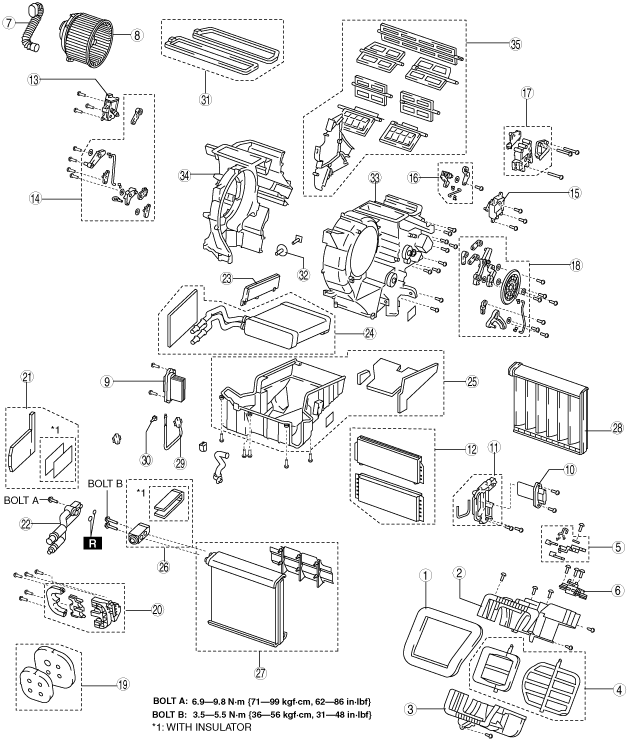
A/C UNIT DISASSEMBLY/ASSEMBLY
id071100800300
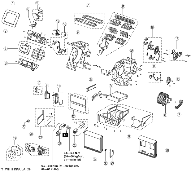
1. Disassemble in the order indicated in the table.
2. Assemble in the reverse order of disassembly.
L.H.D.
am3zzw00008208
|
R.H.D.
am3zzw00006705
|
|
Step |
Part name |
Disassembly/assembly of main parts |
||
|---|---|---|---|---|
|
Heater core |
Evaporator temperature sensor |
Evaporator |
||
|
1
|
Adhesive polyurethane (1)
|
—
|
—
|
—
|
|
2
|
Blower case (1)
|
—
|
—
|
—
|
|
3
|
Blower case (2)
|
—
|
—
|
—
|
|
4
|
Air intake door
|
—
|
—
|
—
|
|
5
|
Air intake link set
|
—
|
—
|
—
|
|
6
|
Air intake actuator
|
—
|
—
|
—
|
|
7
|
Blower motor pipe
|
—
|
—
|
—
|
|
8
|
Blower motor
|
—
|
—
|
—
|
|
9
|
Power MOS FET (Full-auto air conditioner)
|
—
|
—
|
—
|
|
10
|
Resistor (Manual air conditioner)
|
—
|
—
|
—
|
|
11
|
Plate
|
—
|
X
|
X
|
|
12
|
Air filter
|
—
|
X
|
X
|
|
13
|
Driver-side air mix actuator (Full-auto air conditioner)
|
—
|
—
|
—
|
|
14
|
Driver-side air mix link set (Full-auto air conditioner)
|
—
|
—
|
—
|
|
15
|
Passenger-side air mix actuator (Full-auto air conditioner)
|
—
|
—
|
—
|
|
16
|
Passenger-side air mix link set (Full-auto air conditioner)
|
—
|
—
|
—
|
|
17
|
Airflow mode actuator (Full-auto air conditioner)
|
—
|
—
|
—
|
|
18
|
Airflow mode link set
|
—
|
—
|
—
|
|
19
|
Polyurethane foam (1)
|
X
|
X
|
X
|
|
20
|
Plate cover
|
X
|
X
|
X
|
|
21
|
Adhesive polyurethane (2)
|
X
|
X
|
X
|
|
22
|
Evaporator pipe
|
X
|
X
|
X
|
|
23
|
Cover
|
X
|
X
|
X
|
|
24
|
Heater core
|
—
|
X
|
X
|
|
25
|
A/C case (1)
|
—
|
X
|
X
|
|
26
|
Expansion valve
|
—
|
X
|
X
|
|
27
|
Evaporator
|
—
|
—
|
—
|
|
28
|
A/C case (2)
|
—
|
—
|
—
|
|
29
|
Evaporator temperature sensor
|
—
|
—
|
—
|
|
30
|
Clip
|
—
|
—
|
—
|
|
31
|
Polyurethane foam (2)
|
—
|
—
|
—
|
|
32
|
Bolt
|
—
|
—
|
—
|
|
33
|
A/C case (3)
|
—
|
—
|
X
|
|
34
|
A/C case (4)
|
—
|
—
|
X
|
|
35
|
Door damper
|
—
|
—
|
—
|
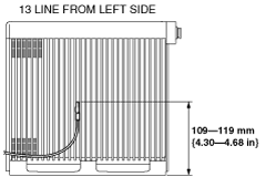
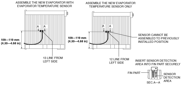
Evaporator Temperature Sensor Assembly Note
MZ-CD 1.6 (Y6)
1. Install the evaporator temperature sensor as shown in the figure.
am3zzw00006706
|
Except MZ-CD 1.6 (Y6)
1. Assemble the evaporator temperature sensor as shown in the figure.
am3uuw00004003
|
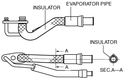
Adhesive Polyurethane (2) Assembly Note
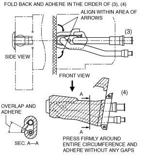
1. Wrap the low-pressure side of the evaporator pipe with insulator. (With insulator)
am3uuw00004004
|
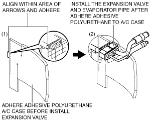
2. Assemble the adhesive polyurethane as shown in the figure.
am3uuw00004005
|
am3zzw00006948
|