AIRFLOW VOLUME CONTROL OPERATION [FULL-AUTO AIR CONDITIONER]
id0740a1102600
Airflow Volume Automatic Control
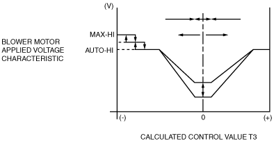
• The climate control unit calculates the blower motor applied voltage characteristic based on the set temperature, ambient temperature, and cabin temperature.
• Compares the differences among this blower motor applied voltage characteristic and the target temperature (Calculated control value T3) and then determines the blower motor applied voltage (AUTO voltage).
• Calculated control value T3 is the difference between the set temperature and temperatures input from the sensors, and is used by the climate control unit to determine the target cabin temperature determined. Calculated control value T3 is constantly calculated according to the set temperature and the signals input from the sensors.
Correction
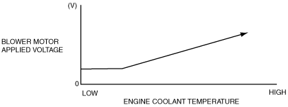
Engine coolant temperature correction (warm-up correction)
• Controls the blower motor applied voltage according to the increase in engine coolant temperature to prevent discomfort caused by a high volume of cold air blown from the vents in winter after starting the engine. However, the engine coolant temperature correction is not performed during defroster correction when the cabin temperature is 20 °C {68 °F} or more and the airflow mode is in VENT mode.
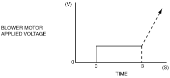
Mild start correction
• Limits blower motor applied voltage for 3 s after the blower motor is started in summer to prevent discomfort caused by a high volume of hot air blown from the vent. However, the mild start correction is not performed when the cabin temperature is 20 °C {68 °F} or less and the airflow is in any mode other than VENT.
MAX HOT and MAX COLD correction
• When the set temperature is at 29.0/84 (MAX HOT) (European (L.H.D. U.K.) specs.), 32.0/90 (MAX HOT) (Australian, General(L.H.D. R.H.D.) specs.), the blower motor applied voltage is fixed at AUTO-HI, and when the set temperature is at 15.0/60 (MAX COLD) (European (L.H.D. U.K.) specs.), 18.0/64 (MAX COLD) (Australian, General(L.H.D. R.H.D.) specs.), the blower motor applied voltage is fixed at MAX-HI. However, MAX HOT correction is not performed during engine coolant correction.
(European (L.H.D. U.K.) specs.)
|
Correction name
|
Set temperature
|
Blower motor applied voltage
|
|
MAX HOT correction
|
29.0
|
12.1 (V): AUTO-HI
|
|
MAX COLD correction
|
15.0
|
14.6 (V): MAX-HI
|
(Australian, General (L.H.D. R.H.D.) specs.)
|
Correction name
|
Set temperature
|
Blower motor applied voltage
|
|
MAX HOT correction
|
32.0
|
12.1 (V): AUTO-HI
|
|
MAX COLD correction
|
18.0
|
14.6 (V): MAX-HI
|
Window fogging prevention correction at start
• Just after engine start, the A/C compressor is not turned on due to PCM A/C cut-off control. As air blows from the defroster when the heater is started, the windows can easily become fogged. To prevent this, blower motor applied voltage is fixed at 0 V for 6 s after the ignition switch is turned to the ON position. However, window fogging prevention correction at start is not performed when the airflow mode is in any mode other than HEAT, DEF/HEAT, or DEFROSTER.
Starting compensation correction
• When the blower motor is started-up at the lowest speed (3.2 V), the blower motor applied voltage is fixed at 4.4 V for 2 s to stabilize blower motor start-up operation.
Defroster correction
• To improve defrosting of the windows, a correction (+2 V) is added to the blower motor applied voltage when the defroster switch is turned on.
Starting burn-out prevention function
• When the blower motor is started-up from the stopped status with a blower motor applied voltage of 4.4 V or more, the blower motor applied voltage is fixed at 4.4 Vfor 1 s to prevent the power MOS FET from burning out due to excessive current.
Airflow Volume Manual Control
• The blower motor applied voltage (airflow volume) can be switched in seven steps with the airflow volume control dial.
|
Airflow volume control dial
|
Blower motor applied voltage
|
|
1st
|
4.3 V
|
|
2nd
|
5.9 V
|
|
3rd
|
7.4 V
|
|
4th
|
9.1 V
|
|
5th
|
10.6 V
|
|
6th
|
12.1 V
|
|
7th
|
14.6 V
|