 |
am3zzw00008886
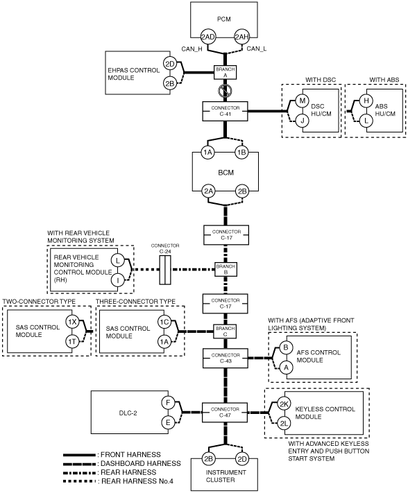
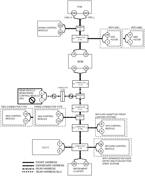
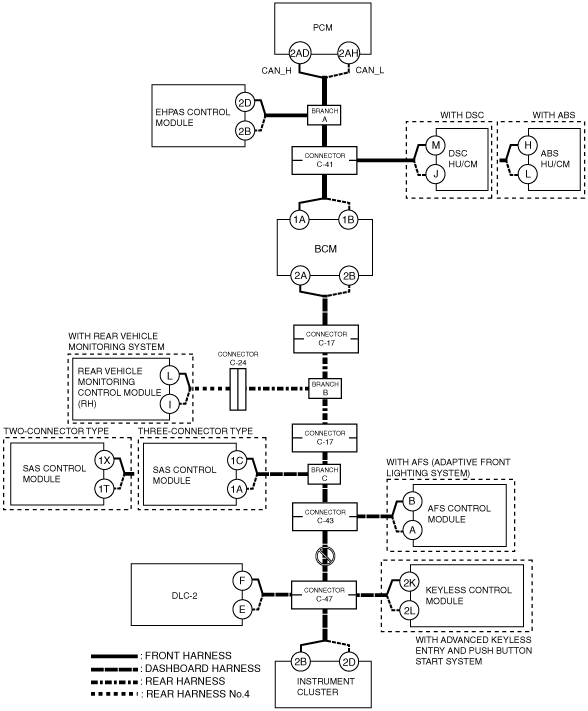
DETERMINING MALFUNCTIONING PART (HS-CAN) [MULTIPLEX COMMUNICATION SYSTEM (R.H.D. (MZR-CD 2.2))]
id0902k5846700
1. Verify the CAN system-related module DTCs and the failed module on the M-MDS screen.
2. Refer to “DTC Output Pattern and Malfunctioning Part“ and find the area linked from the malfunctioning part.
3. Inspect the possible cause and inspection item of the applicable malfunctioning part.
4. Perform the DTC inspection after the repair procedure.
DTC Output Pattern and Malfunctioning Part
|
M-MDS display |
DTC display pattern |
|||||||||||||||
|---|---|---|---|---|---|---|---|---|---|---|---|---|---|---|---|---|
|
DTC output module |
DTC |
|||||||||||||||
|
PCM
(PCM)
|
U0121:00
|
|
|
|
×
|
×
|
|
|
|
|
|
|
|
|
|
|
|
U0155:00
|
|
|
|
|
|
|
|
|
|
|
|
|
|
|
×
|
|
|
EPS
(EHPAS control module)
|
U0100
|
×
|
|
|
|
|
|
|
|
|
|
|
|
|
|
|
|
U0140
|
|
|
|
|
|
|
|
|
|
|
|
|
|
|
|
|
|
U0155
|
|
|
|
|
|
|
|
|
|
|
|
|
|
|
×
|
|
|
U2023
|
-
|
|
|
|
|
|
|
|
|
|
|
|
|
|
|
|
|
ABS*1
(DSC HU/CM)
|
U0100:00
|
×
|
|
×
|
|
|
|
|
|
|
|
|
|
|
|
|
|
U0140:00
|
|
|
|
|
|
|
|
|
|
|
|
|
|
|
|
|
|
U0155:00
|
|
|
|
|
|
|
|
|
|
|
|
|
|
|
×
|
|
|
U0401:00
|
-
|
|
-
|
|
|
|
|
|
|
|
|
|
|
|
|
|
|
U0402:00
|
-
|
|
-
|
|
|
|
|
|
|
|
|
|
|
|
|
|
|
U0422:00
|
|
|
|
|
|
|
|
|
|
|
|
|
|
|
|
|
|
U0428:62
|
|
|
|
|
|
|
|
|
|
|
|
|
|
|
|
|
|
U0428:64
|
|
|
|
|
|
|
|
|
|
|
|
|
|
|
|
|
|
ABS*2
(ABS HU/CM)
|
U0100:00
|
×
|
|
×
|
|
|
|
|
|
|
|
|
|
|
|
|
|
U0155:00
|
|
|
|
|
|
|
|
|
|
|
|
|
|
|
×
|
|
|
GEM
(BCM)
|
U0100:00
|
×
|
|
×
|
|
|
×
|
|
|
|
|
|
|
|
|
|
|
U0121:00
|
|
|
|
×
|
×
|
×
|
|
|
|
|
|
|
|
|
|
|
|
U0151:00
|
|
|
|
|
|
|
|
|
|
×
|
|
|
|
|
|
|
|
U0214:00
|
|
|
|
|
|
|
|
|
|
|
|
|
|
×
|
|
|
|
U0401:68
|
-
|
|
-
|
|
|
-
|
|
|
|
|
|
|
|
|
|
|
|
RVM*3
(Rear vehicle monitoring control module (RH))
|
U0100:00
|
×
|
|
×
|
|
|
×
|
×
|
|
|
|
|
|
|
|
|
|
U0121:00
|
|
|
|
×
|
×
|
×
|
×
|
|
|
|
|
|
|
|
|
|
|
U0140:00
|
|
|
|
|
|
|
×
|
|
|
|
|
|
|
|
|
|
|
U0155:00
|
|
|
|
|
|
|
|
|
|
|
|
|
|
|
×
|
|
|
U0401:68
|
-
|
|
-
|
|
|
-
|
-
|
|
|
|
|
|
|
|
|
|
|
U0415:68
|
|
|
|
-
|
-
|
-
|
-
|
|
|
|
|
|
|
|
|
|
|
RCM
(SAS control module)
|
U0155
|
|
|
|
|
|
|
|
|
|
|
|
|
|
|
×
|
|
AFS*4
(AFS control module)
|
U0100:00
|
×
|
|
×
|
|
|
×
|
×
|
|
×
|
|
×
|
|
|
|
|
|
U0140:00
|
|
|
|
|
|
|
×
|
|
×
|
|
×
|
|
|
|
|
|
|
RKE*5
(Keyless control module)
|
U0100:00
|
×
|
|
×
|
|
|
×
|
×
|
|
×
|
|
×
|
|
×
|
|
|
|
U0121:00
|
|
|
|
×
|
×
|
×
|
×
|
|
×
|
|
×
|
|
×
|
|
|
|
|
IC
(Instrument cluster)
|
U0100:00
|
×
|
|
×
|
|
|
×
|
×
|
|
×
|
|
×
|
|
×
|
|
|
|
U0100:87
|
-
|
|
-
|
|
|
-
|
-
|
|
-
|
|
-
|
|
-
|
|
|
|
|
U0121:00
|
|
|
|
×
|
×
|
×
|
×
|
|
×
|
|
×
|
|
×
|
|
|
|
|
U0131:00
|
|
×
|
×
|
|
|
×
|
×
|
|
×
|
|
×
|
|
×
|
|
|
|
|
U0140:00
|
|
|
|
|
|
|
×
|
|
×
|
|
×
|
|
×
|
|
|
|
|
U0151:00
|
|
|
|
|
|
|
|
|
|
×
|
×
|
|
×
|
|
|
|
|
U0182:00
|
|
|
|
|
|
|
|
|
|
|
|
×
|
×
|
|
|
|
|
U0214:00
|
|
|
|
|
|
|
|
|
|
|
|
|
|
×
|
|
|
|
U0232:00
|
|
|
|
|
|
|
|
×
|
×
|
|
×
|
|
×
|
|
|
|
|
U0401:68
|
-
|
|
-
|
|
|
-
|
-
|
|
-
|
|
-
|
|
-
|
|
|
|
|
U0401:92
|
-
|
|
-
|
|
|
-
|
-
|
|
-
|
|
-
|
|
-
|
|
|
|
|
U0415:68
|
|
|
|
-
|
-
|
-
|
-
|
|
-
|
|
-
|
|
-
|
|
|
|
|
U0415:92
|
|
|
|
-
|
-
|
-
|
-
|
|
-
|
|
-
|
|
-
|
|
|
|
|
U0452:92
|
|
|
|
|
|
|
|
|
|
-
|
-
|
|
-
|
|
|
|
|
U0483:68
|
|
|
|
|
|
|
|
|
|
|
|
-
|
-
|
|
|
|
|
U0483:92
|
|
|
|
|
|
|
|
|
|
|
|
-
|
-
|
|
|
|
|
U0515:68
|
|
|
|
|
|
|
|
|
|
|
|
|
|
-
|
|
|
|
U0515:92
|
|
|
|
|
|
|
|
|
|
|
|
|
|
-
|
|
|
|
U0533:68
|
|
|
|
|
|
|
|
-
|
-
|
|
-
|
|
-
|
|
|
|
|
U2005:86
|
-
|
|
-
|
|
|
-
|
-
|
|
-
|
|
-
|
|
-
|
|
|
|
|
M-MDS display module
|
“Fail” display pattern
|
|||||||||||||||
|
PCM
|
×
|
|
×
|
|
|
×
|
×
|
|
×
|
|
×
|
|
×
|
|
|
|
|
EPS
|
|
×
|
×
|
|
|
×
|
×
|
|
×
|
|
×
|
|
×
|
|
|
|
|
ABS*1
|
|
|
|
×
|
|
×
|
×
|
|
×
|
|
×
|
|
×
|
|
|
|
|
ABS*2
|
|
|
|
|
×
|
×
|
×
|
|
×
|
|
×
|
|
×
|
|
|
|
|
GEM
|
|
|
|
|
|
|
×
|
|
×
|
|
×
|
|
×
|
|
|
|
|
RVM*3
|
|
|
|
|
|
|
|
×
|
×
|
|
×
|
|
×
|
|
|
|
|
RCM
|
|
|
|
|
|
|
|
|
|
×
|
×
|
|
×
|
|
|
|
|
AFS*4
|
|
|
|
|
|
|
|
|
|
|
|
×
|
×
|
|
|
|
|
RKE*5
|
|
|
|
|
|
|
|
|
|
|
|
|
|
×
|
|
|
|
IC
|
|
|
|
|
|
|
|
|
|
|
|
|
|
|
×
|
|
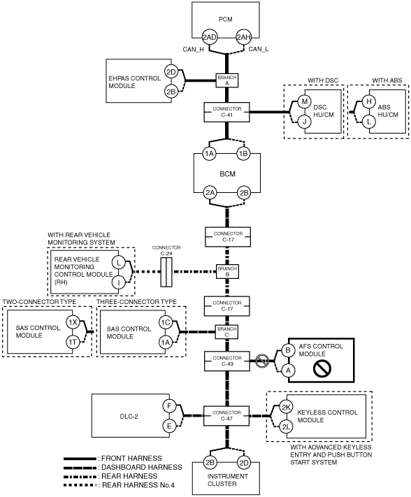
A
Possible cause
System wiring diagram
am3zzw00008886
|
Inspection item
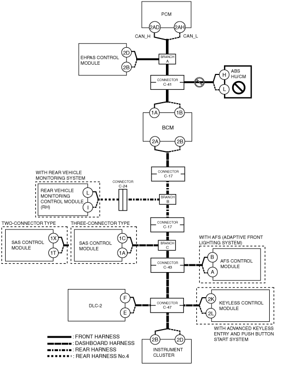
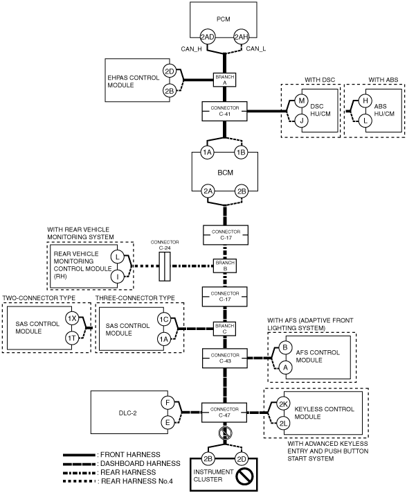
B
Possible cause
System wiring diagram
am3zzw00008887
|
Inspection item
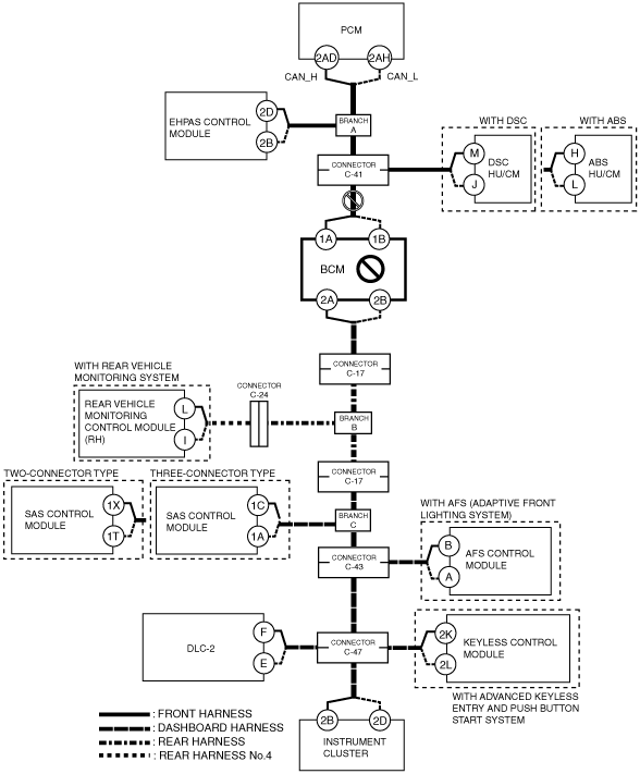
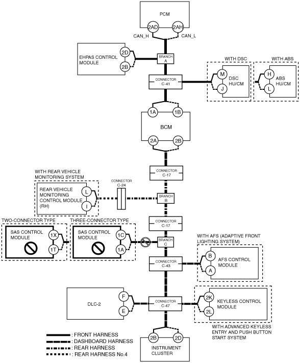
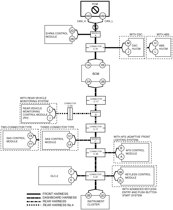
C
Possible cause
System wiring diagram
am3zzw00008888
|
Inspection item
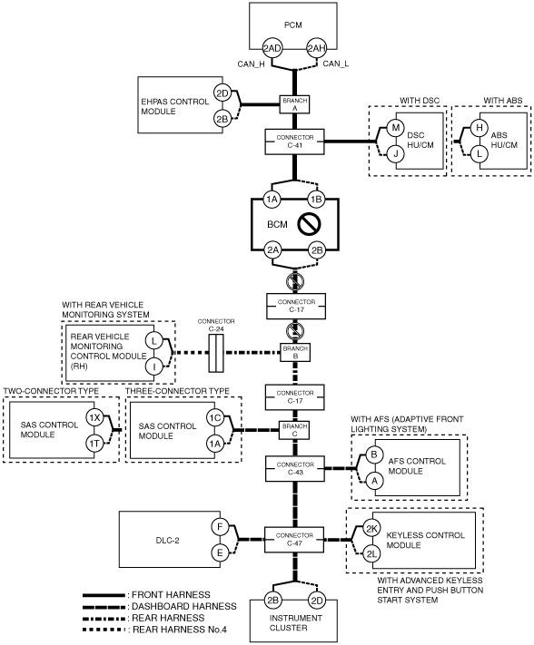
D
Possible cause
System wiring diagram
am3zzw00008889
|
Inspection item
E
Possible cause
System wiring diagram
am3zzw00008890
|
Inspection item
F
Possible cause
System wiring diagram
am3zzw00008891
|
Inspection item
G
Possible cause
System wiring diagram
am3zzw00008892
|
Inspection item
H
Possible cause
System wiring diagram
am3zzw00008893
|
Inspection item
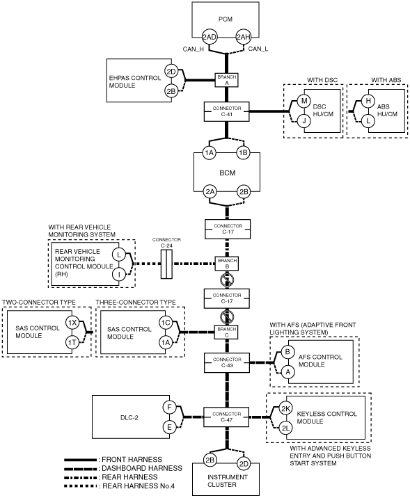
I
Possible cause
System wiring diagram
am3zzw00008894
|
Inspection item
J
Possible cause
System wiring diagram
am3zzw00008895
|
Inspection item
K
Possible cause
System wiring diagram
am3zzw00008896
|
Inspection item
L
Possible cause
System wiring diagram
am3zzw00008897
|
Inspection item
M
Possible cause
System wiring diagram
am3zzw00008898
|
Inspection item
N
Possible cause
System wiring diagram
am3zzw00008899
|
Inspection item
O
Possible cause
System wiring diagram
am3zzw00008900
|
Inspection item