 |
am3zzw00008851
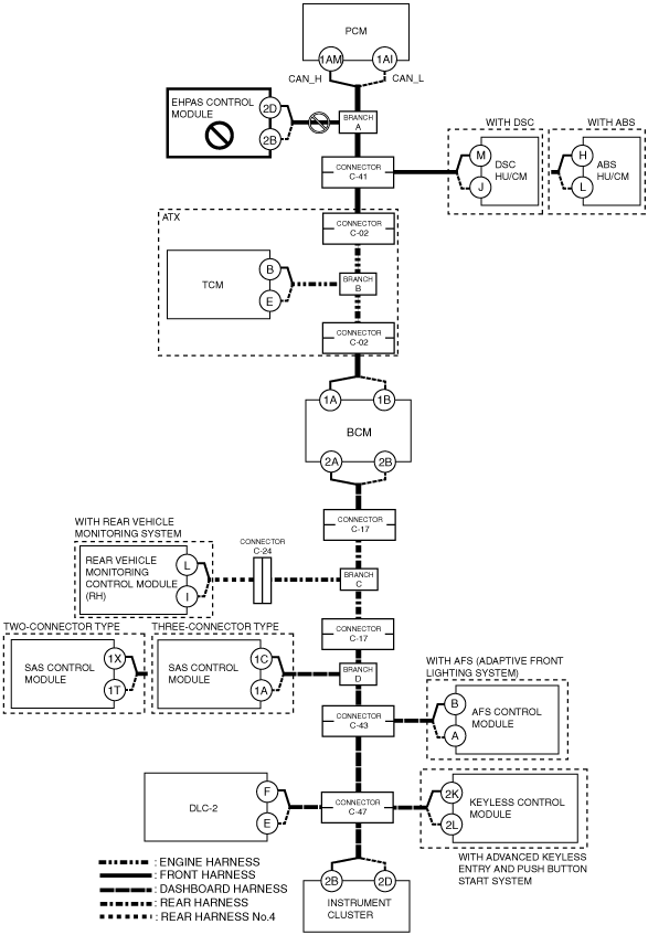
DETERMINING MALFUNCTIONING PART (HS-CAN) [MULTIPLEX COMMUNICATION SYSTEM (R.H.D. (MZR 2.0 DISI i-stop))]
id0902k8846700
1. Verify the CAN system-related module DTCs and the failed module on the M-MDS screen.
2. Refer to “DTC Output Pattern and Malfunctioning Part” and find the area linked from the malfunctioning part.
3. Inspect the possible cause and inspection item of the applicable malfunctioning part.
4. Perform the DTC inspection after the repair procedure.
DTC Output Pattern and Malfunctioning Part
|
M-MDS display |
DTC display pattern |
|||||||||||||||||
|---|---|---|---|---|---|---|---|---|---|---|---|---|---|---|---|---|---|---|
|
DTC output module |
DTC |
|||||||||||||||||
|
PCM
(PCM)
|
U0101:00
|
|
|
|
|
|
|
×
|
|
|
|
|
|
|
|
|
|
|
|
U0121:00
|
|
|
|
×
|
×
|
|
|
|
|
|
|
|
|
|
|
|
|
|
|
U0131:00
|
|
×
|
|
|
|
|
|
|
|
|
|
|
|
|
|
|
|
|
|
U0140:00
|
|
|
|
|
|
|
|
|
|
|
|
|
|
|
|
|
|
|
|
U0155:00
|
|
|
|
|
|
|
|
|
|
|
|
|
|
|
|
|
×
|
|
|
U0214:00
|
|
|
|
|
|
|
|
|
|
|
|
|
|
|
|
×
|
|
|
|
EPS
(EHPAS control module)
|
U0100
|
×
|
|
|
|
|
|
|
|
|
|
|
|
|
|
|
|
|
|
U0140
|
|
|
|
|
|
|
|
|
|
|
|
|
|
|
|
|
|
|
|
U0155
|
|
|
|
|
|
|
|
|
|
|
|
|
|
|
|
|
×
|
|
|
U0401
|
-
|
|
|
|
|
|
|
|
|
|
|
|
|
|
|
|
|
|
|
U2023
|
-
|
|
|
|
|
|
|
|
|
|
|
|
|
|
|
|
|
|
|
ABS*1
(DSC HU/CM)
|
U0100:00
|
×
|
|
×
|
|
|
|
|
|
|
|
|
|
|
|
|
|
|
|
U0101:00
|
|
|
|
|
|
|
×
|
|
|
|
|
|
|
|
|
|
|
|
|
U0140:00
|
|
|
|
|
|
|
|
|
|
|
|
|
|
|
|
|
|
|
|
U0155:00
|
|
|
|
|
|
|
|
|
|
|
|
|
|
|
|
|
×
|
|
|
U0401:00
|
-
|
|
-
|
|
|
|
|
|
|
|
|
|
|
|
|
|
|
|
|
U0402:00
|
-*7
|
|
-*7
|
|
|
|
-*3
|
|
|
|
|
|
|
|
|
|
|
|
|
U0422:00
|
|
|
|
|
|
|
|
|
|
|
|
|
|
|
|
|
|
|
|
U0428:62
|
|
|
|
|
|
|
|
|
|
|
|
|
|
|
|
|
|
|
|
U0428:64
|
|
|
|
|
|
|
|
|
|
|
|
|
|
|
|
|
|
|
|
ABS*2
(ABS HU/CM)
|
U0100:00
|
×
|
|
×
|
|
|
|
|
|
|
|
|
|
|
|
|
|
|
|
U0155:00
|
|
|
|
|
|
|
|
|
|
|
|
|
|
|
|
|
×
|
|
|
TCM*3
(TCM)
|
U0100:00
|
×
|
|
×
|
|
|
×
|
|
|
|
|
|
|
|
|
|
|
|
|
U0121:00
|
|
|
|
×
|
×
|
×
|
|
|
|
|
|
|
|
|
|
|
|
|
|
GEM
(BCM)
|
U0100:00
|
×
|
|
×
|
|
|
×
|
|
×
|
|
|
|
|
|
|
|
|
|
|
U0101:00
|
|
|
|
|
|
|
×
|
×
|
|
|
|
|
|
|
|
|
|
|
|
U0121:00
|
|
|
|
×
|
×
|
×
|
|
×
|
|
|
|
|
|
|
|
|
|
|
|
U0151:00
|
|
|
|
|
|
|
|
|
|
|
|
×
|
|
|
|
|
|
|
|
U0214:00
|
|
|
|
|
|
|
|
|
|
|
|
|
|
|
|
×
|
|
|
|
U0401:68
|
-
|
|
-
|
|
|
-
|
|
-
|
|
|
|
|
|
|
|
|
|
|
|
RVM*4
(Rear vehicle monitoring control module (RH))
|
U0100:00
|
×
|
|
×
|
|
|
×
|
|
×
|
×
|
|
|
|
|
|
|
|
|
|
U0101:00
|
|
|
|
|
|
|
×
|
×
|
×
|
|
|
|
|
|
|
|
|
|
|
U0121:00
|
|
|
|
×
|
×
|
×
|
|
×
|
×
|
|
|
|
|
|
|
|
|
|
|
U0140:00
|
|
|
|
|
|
|
|
|
×
|
|
|
|
|
|
|
|
|
|
|
U0155:00
|
|
|
|
|
|
|
|
|
|
|
|
|
|
|
|
|
×
|
|
|
U0401:68
|
-
|
|
-
|
|
|
-
|
|
|
|
|
|
|
|
|
|
|
|
|
|
U0402:68
|
-*7
|
|
-*7
|
|
|
-*7
|
-*3
|
|
-
|
|
|
|
|
|
|
|
|
|
|
U0415:68
|
|
|
|
-
|
-
|
-
|
|
-
|
-
|
|
|
|
|
|
|
|
|
|
|
RCM
(SAS control module)
|
U0155
|
|
|
|
|
|
|
|
|
|
|
|
|
|
|
|
|
×
|
|
AFS*5
(AFS control module)
|
U0100:00
|
×
|
|
×
|
|
|
×
|
|
×
|
×
|
|
×
|
|
×
|
|
|
|
|
|
U0140:00
|
|
|
|
|
|
|
|
|
×
|
|
×
|
|
×
|
|
|
|
|
|
|
RKE*6
(Keyless control module)
|
U0100:00
|
×
|
|
×
|
|
|
×
|
|
×
|
×
|
|
×
|
|
×
|
|
×
|
|
|
|
U0101:00
|
|
|
|
|
|
|
×
|
×
|
×
|
|
×
|
|
×
|
|
×
|
|
|
|
|
U0121:00
|
|
|
|
×
|
×
|
×
|
|
×
|
×
|
|
×
|
|
×
|
|
×
|
|
|
|
|
IC
(Instrument cluster)
|
U0100:00
|
×
|
|
×
|
|
|
×
|
|
×
|
×
|
|
×
|
|
×
|
|
×
|
|
|
|
U0100:87
|
-
|
|
-
|
|
|
-
|
|
-
|
-
|
|
-
|
|
-
|
|
-
|
|
|
|
|
U0101:00
|
|
|
|
|
|
|
×
|
×
|
×
|
|
×
|
|
×
|
|
×
|
|
|
|
|
U0121:00
|
|
|
|
×
|
×
|
×
|
|
×
|
×
|
|
×
|
|
×
|
|
×
|
|
|
|
|
U0131:00
|
|
×
|
×
|
|
|
×
|
|
×
|
×
|
|
×
|
|
×
|
|
×
|
|
|
|
|
U0140:00
|
|
|
|
|
|
|
|
|
×
|
|
×
|
|
×
|
|
×
|
|
|
|
|
U0151:00
|
|
|
|
|
|
|
|
|
|
|
|
×
|
×
|
|
×
|
|
|
|
|
U0182:00
|
|
|
|
|
|
|
|
|
|
|
|
|
|
×
|
×
|
|
|
|
|
U0214:00
|
|
|
|
|
|
|
|
|
|
|
|
|
|
|
|
×
|
|
|
|
U0232:00
|
|
|
|
|
|
|
|
|
|
×
|
×
|
|
×
|
|
×
|
|
|
|
|
U0401:68
|
-
|
|
-
|
|
|
-
|
|
-
|
-
|
|
-
|
|
-
|
|
-
|
|
|
|
|
U0401:92
|
-
|
|
-
|
|
|
-
|
|
-
|
-
|
|
-
|
|
-
|
|
-
|
|
|
|
|
U0402:68
|
|
|
|
|
|
|
-
|
-
|
-
|
|
-
|
|
-
|
|
-
|
|
|
|
|
U0402:92
|
|
|
|
|
|
|
-
|
-
|
-
|
|
-
|
|
-
|
|
-
|
|
|
|
|
U0415:68
|
|
|
|
-
|
-
|
-
|
|
-
|
-
|
|
-
|
|
-
|
|
-
|
|
|
|
|
U0415:92
|
|
|
|
-
|
-
|
-
|
|
-
|
-
|
|
-
|
|
-
|
|
-
|
|
|
|
|
U0452:92
|
|
|
|
|
|
|
|
|
|
|
|
-
|
-
|
|
-
|
|
|
|
|
U0483:68
|
|
|
|
|
|
|
|
|
|
|
|
|
|
-
|
-
|
|
|
|
|
U0483:92
|
|
|
|
|
|
|
|
|
|
|
|
|
|
-
|
-
|
|
|
|
|
U0515:68
|
|
|
|
|
|
|
|
|
|
|
|
|
|
|
|
-
|
|
|
|
U0515:92
|
|
|
|
|
|
|
|
|
|
|
|
|
|
|
|
-
|
|
|
|
U0533:68
|
|
|
|
|
|
|
|
|
|
-
|
-
|
|
-
|
|
-
|
|
|
|
|
U2005:86
|
-
|
|
-
|
|
|
-
|
|
-
|
-
|
|
-
|
|
-
|
|
-
|
|
|
|
|
M-MDS display module
|
“Fail” display pattern
|
|||||||||||||||||
|
PCM
|
×
|
|
×
|
|
|
×
|
|
×
|
×
|
|
×
|
|
×
|
|
×
|
|
|
|
|
EPS
|
|
×
|
×
|
|
|
×
|
|
×
|
×
|
|
×
|
|
×
|
|
×
|
|
|
|
|
ABS*1
|
|
|
|
×
|
|
×
|
|
×
|
×
|
|
×
|
|
×
|
|
×
|
|
|
|
|
ABS*2
|
|
|
|
|
×
|
×
|
|
×
|
×
|
|
×
|
|
×
|
|
×
|
|
|
|
|
TCM*3
|
|
|
|
|
|
|
×
|
×
|
×
|
|
×
|
|
×
|
|
×
|
|
|
|
|
GEM
|
|
|
|
|
|
|
|
|
×
|
|
×
|
|
×
|
|
×
|
|
|
|
|
RVM*4
|
|
|
|
|
|
|
|
|
|
×
|
×
|
|
×
|
|
×
|
|
|
|
|
RCM
|
|
|
|
|
|
|
|
|
|
|
|
×
|
×
|
|
×
|
|
|
|
|
AFS*5
|
|
|
|
|
|
|
|
|
|
|
|
|
|
×
|
×
|
|
|
|
|
RKE*6
|
|
|
|
|
|
|
|
|
|
|
|
|
|
|
|
×
|
|
|
|
IC
|
|
|
|
|
|
|
|
|
|
|
|
|
|
|
|
|
×
|
|
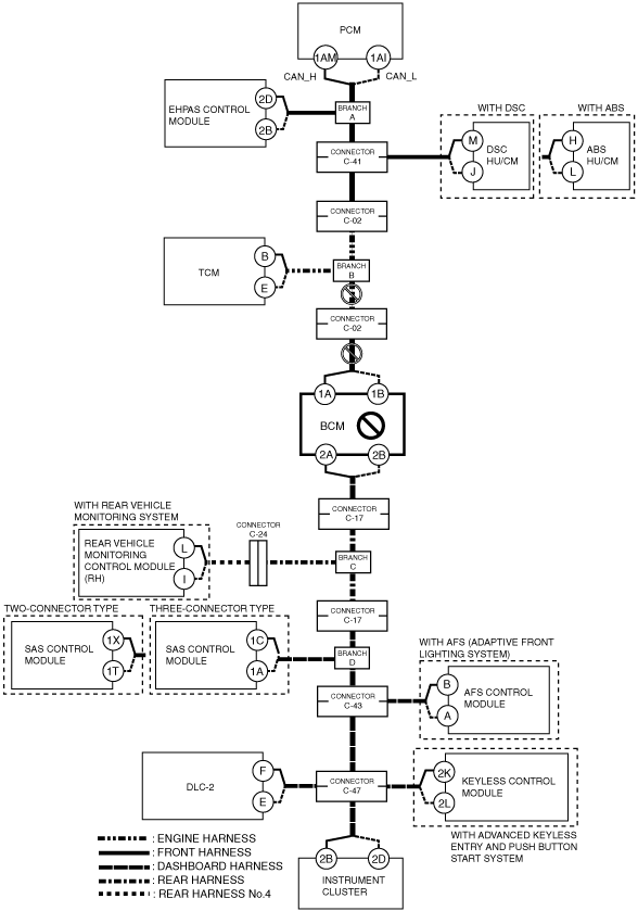
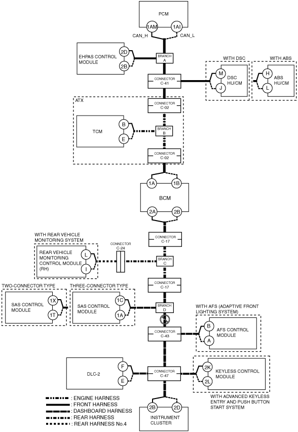
A
Possible cause
System wiring diagram
am3zzw00008851
|
Inspection item
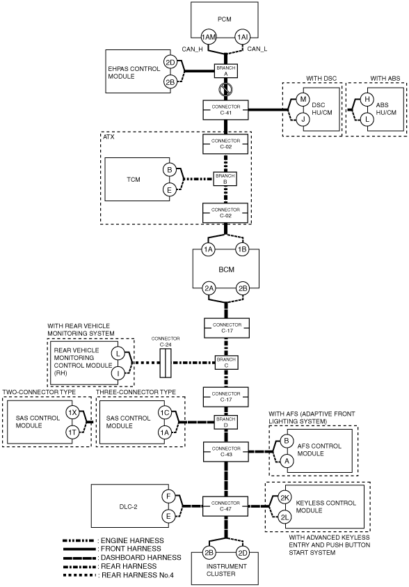
B
Possible cause
System wiring diagram
am3zzw00008852
|
Inspection item
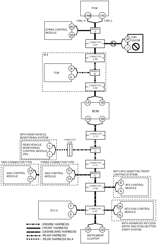
C
Possible cause
System wiring diagram
am3zzw00008853
|
Inspection item
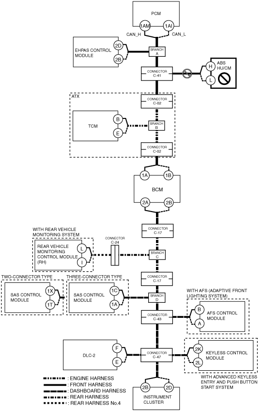
D
Possible cause
System wiring diagram
am3zzw00008854
|
Inspection item
E
Possible cause
System wiring diagram
am3zzw00008855
|
Inspection item
F
Possible cause
System wiring diagram
am3zzw00009982
|
Inspection item
G
Possible cause
System wiring diagram
am3zzw00009983
|
Inspection item
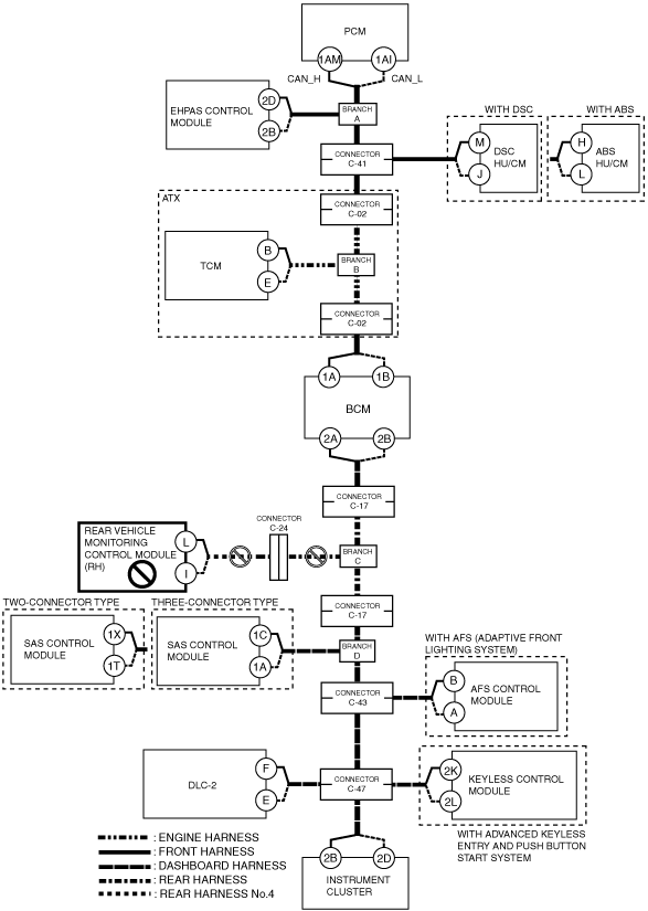
H
ATX
System wiring diagram
am3zzw00009984
|
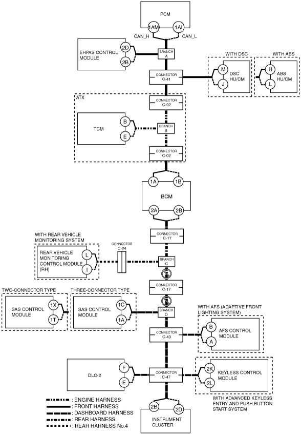
MTX
System wiring diagram
am3zzw00008856
|
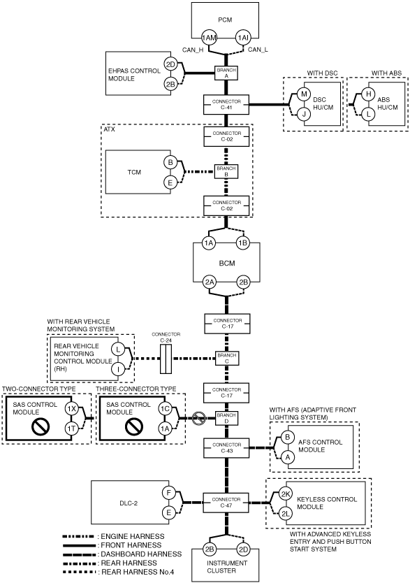
I
Possible cause
System wiring diagram
am3zzw00008857
|
Inspection item
J
Possible cause
System wiring diagram
am3zzw00008858
|
Inspection item
K
Possible cause
System wiring diagram
am3zzw00008859
|
Inspection item
L
Possible cause
System wiring diagram
am3zzw00008860
|
Inspection item
M
Possible cause
System wiring diagram
am3zzw00008861
|
Inspection item
N
Possible cause
System wiring diagram
am3zzw00008862
|
Inspection item
O
Possible cause
System wiring diagram
am3zzw00008863
|
Inspection item
P
Possible cause
System wiring diagram
am3zzw00008864
|
Inspection item
Q
Possible cause
System wiring diagram
am3zzw00008865
|
Inspection item