 |
am3zzw00007029
POWER OUTER MIRROR INSPECTION
id091200420900
Mirror Glass Adjustment, Retract/Return
1. Disconnect the negative battery cable.
2. Remove the inner garnish. (See INNER GARNISH REMOVAL/INSTALLATION.)
3. Disconnect the power outer mirror connector.
4. Remove the front door trim. (See FRONT DOOR TRIM REMOVAL/INSTALLATION.)
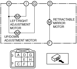
5. Apply battery positive voltage and connect the ground to the power outer mirror terminals and inspect the power outer mirror operation.
am3zzw00007029
|
|
Mirror operation direction |
Terminal |
|
|---|---|---|
|
B+ |
Ground |
|
|
Up
|
G
|
H
|
|
Down
|
H
|
G
|
|
Left
|
I
|
H
|
|
Right
|
H
|
I
|
|
Retract
|
F
|
D
|
|
Return
|
D
|
F
|
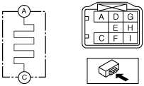
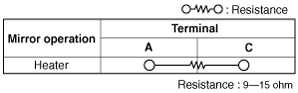
Heated Outer Mirror
1. Disconnect the negative battery cable.
2. Remove the inner garnish. (See INNER GARNISH REMOVAL/INSTALLATION.)
3. Disconnect the power outer mirror connector.
4. Remove the front door trim. (See FRONT DOOR TRIM REMOVAL/INSTALLATION.)
5. Apply battery voltage to power outer mirror connector terminal A, and connect terminal C to ground.
am3uuw00003632
|
am3uuw00003633
|
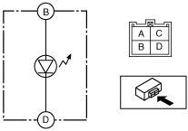
RVM Warning Indicator
1. Disconnect the negative battery cable.
2. Remove the inner garnish. (See INNER GARNISH REMOVAL/INSTALLATION.)
3. Disconnect the power outer mirror connector.
4. Remove the front door trim. (See FRONT DOOR TRIM REMOVAL/INSTALLATION.)
5. Apply battery voltage to power outer mirror connector terminal B, and connect terminal D to ground.
am3zzw00007030
|
6. Verify that the RVM warning indicator light illuminates.