am6xun00000791
|
ON-BOARD DIAGNOSIS SYSTEM (ADVANCED KEYLESS ENTRY AND PUSH BUTTON START SYSTEM) MALFUNCTION DIAGNOSIS FUNCTION
id091400601500
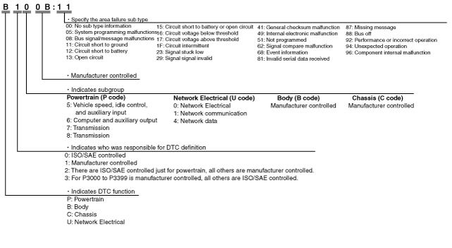
DTC 7-Digit Code Definition
am6xun00000791
|
On-board Diagnostic Function
Malfunction detection function
|
DTC |
Description |
|---|---|
|
Mazda Modular Diagnostic System (M-MDS) display |
|
|
B100B:11
|
Short to ground in steering lock unit ground circuit
|
|
B100B:15
|
Open circuit or short to power supply in steering lock unit ground circuit
|
|
B100C:11
|
Short to ground in steering lock unit power supply circuit
|
|
B100C:12
|
Short to power supply in steering lock unit power supply circuit
|
|
B1026:08
|
Receiving erratic signal from steering lock unit
|
|
B1026:51
|
Steering lock unit programming error
|
|
B1026:71
|
Steering lock unit malfunction
|
|
B1026:87
|
Communication error between keyless control module and steering lock unit
|
|
B1026:92
|
Incorrect operation of steering lock unit
|
|
B1026:96
|
Steering lock unit internal malfunction
|
|
B102B:51
|
No programmed transmitter
|
|
B108B:23
|
Short to ground in push button start 1 circuit
|
|
B108B:29
|
Mismatch state of push button start 1 and 2
|
|
B108C:23
|
Short to ground in push button start 2 circuit
|
|
B10C6:1F
|
Erratic signal of keyless antenna (exterior, rear)
|
|
B10C7:1F
|
Erratic signal of keyless antenna (interior, rear)
|
|
B10C9:1F
|
Erratic signal of keyless antenna (interior, front)
|
|
B10E7:11
|
Short to ground in IG1 relay circuit
|
|
B10E7:12
|
Short to power supply in IG1 relay circuit
|
|
B10E7:16
|
Low voltage in IG1 monitor input circuit
|
|
B10E7:17
|
High voltage in IG1 monitor input circuit
|
|
B112A:11
|
Short to ground in IG2 relay circuit
|
|
B112A:12
|
Short to power supply in IG2 relay circuit
|
|
B112A:16
|
Low voltage in IG2 monitor input circuit
|
|
B112A:17
|
High voltage in IG2 monitor input circuit
|
|
B1140:29*3
|
Erratic signal of starter interlock switch
|
|
B11FD:1F
|
Erratic signal of keyless antenna (exterior, LF)
|
|
B1210:1F
|
Erratic signal of keyless antenna (exterior, RF)
|
|
B1239:1F*4
|
Erratic signal of keyless antenna (interior, glove compartment)
|
|
C0040:29*2
|
Erratic signal of brake switch
|
|
P0560:16
|
Low voltage in power supply circuit (+B3)
|
|
P0560:17
|
High voltage in power supply circuit (+B3)
|
|
P0615:11
|
Short to ground in starter relay circuit
|
|
P0615:12
|
Short to power supply in starter relay circuit
|
|
P0615:13
|
Open circuit in starter relay circuit
|
|
P081C:62*2
|
Mis-match signal between CAN and P range switch
|
|
P081D:62*1
|
Mis-match signal between CAN and neutral switch
|
|
P0830:23*1
|
Short to ground in CPP switch circuit
|
|
P0850:29*2
|
Erratic signal of TR switch
|
|
P1708:29*1
|
Erratic signal of CPP switch and/or starter interlock switch
|
|
P1794:16
|
Low voltage in power supply circuit (+B2)
|
|
P1794:17
|
High voltage in power supply circuit (+B2)
|
|
U0001:88
|
Keyless control module communication error (HS-CAN)
|
|
U0028:87
|
Communication error with BCM
|
|
U0100:00
|
Communication error with PCM
|
|
U0101:00*2
|
Communication error with TCM
|
|
U0121:00
|
Communication error with DSC HU/CM
|
|
U0401:68
|
Receiving erratic data from PCM
|
|
U0415:68
|
Receiving erratic data from DSC HU/CM
|
|
U201F:11
|
Short to ground in keyless receiver circuit
|
|
U2100:00
|
Incomplete configuration
|
|
U3000:49
|
Keyless control module internal malfunction
|
|
U3000:96
|
Keyless control module internal malfunction
|
|
U3003:16
|
Low voltage in power supply circuit (+B1)
|
|
U3003:17
|
High voltage in power supply circuit (+B1)
|
|
U3004:11
|
Short to ground in ACC relay circuit
|
|
U3004:12
|
Short to power supply in ACC relay circuit
|
|
U3004:16
|
Low voltage in ACC monitor input circuit
|
|
U3004:17
|
High voltage in ACC monitor input circuit
|
Vehicles With Immobilizer System
|
DTC |
Description |
|
|---|---|---|
|
Mazda Modular Diagnostic System (M-MDS) display |
Security light flashing pattern |
|
|
B10D5:13
|
 |
Coil antenna malfunction
|
|
B10D7:05
|
 |
Key ID number error
|
|
B10D7:51
|
 |
Unprogrammed key ID number
|
|
B10D7:81
|
 |
Receiving erratic serial data
|
|
B10D7:94
|
|
Key ID number error
|
|
B10D8:00
|
 |
Shortage of programmed key
|
|
B10D9:87
|
 |
Communication error with coil antenna
|
|
B10DA:51
|
 |
Communication error with PCM (Data transfer failure)
|
|
B10DA:62
|
 |
Communication error with PCM (Data mis-match)
|
|
B10E6:11
|
Not illuminated
|
Short to ground in coil antenna power supply circuit
|
|
B10E6:12
|
Not illuminated
|
Short to power supply in coil antenna power supply circuit
|
|
U0100:87
|
 |
Communication error with PCM (No response)
|
Fail-safe Function
am3zzn00002358
|