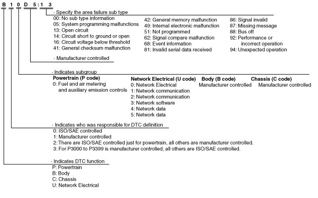
INSTRUMENT CLUSTER ON-BOARD DIAGNOSTIC OPERATION


id092200468500


Malfunction Detection Function

•  If a malfunction occurs in the input/output signals, other units, or the CAN system, it is recorded as a DTC. Recorded DTCs can be read by the Mazda Modular Diagnostic System (M-MDS).

DTC 7-digit code definition

•  When related systems or components have failed, the CM stores the DTC of the malfunctioning part in the CM memory, and allows for the retrieval of the store data using scanning tool when necessary. The DTCs are indicated using seven digits. Each digit indicates the following.
am6xun00000789


DTC table

DTC No.

Description

B10D5:13*1
Coil antenna malfunction
B10D7:05*1
Key ID number error
B10D7:51*1
Unprogrammed key ID number
B10D7:81*1
Receiving erratic serial data
B10D7:94*1
Key ID number error
B10D8:00*1
Shortage of programmed key
B10D9:87*1
Communication error with coil antenna
B10DA:51*1
Communication error with PCM (Data transfer failure)
B10DA:62*1
Communication error with PCM (Data mis-match)
B1A84:41
Configuration error
B1A84:51
Configuration error
C0077:00*2
Low tire pressure
C2011:49*2
Wheel unit No.1 internal malfunction
C2012:49*2
Wheel unit No.2 internal malfunction
C2013:49*2
Wheel unit No.3 internal malfunction
C2014:49*2
Wheel unit No.4 internal malfunction
C2011:87*2
Wheel unit No.1 (No response)
C2012:87*2
Wheel unit No.2 (No response)
C2013:87*2
Wheel unit No.3 (No response)
C2014:87*2
Wheel unit No.4 (No response)
U0001:88
Module communication error (HS-CAN)
U0010:88
Module communication error (MS-CAN)
U0100:00
Communication error with PCM
U0100:87*1
Communication error with PCM (No response)
U0101:00*3
Communication error with TCM
U0121:00
Communication error with DSC HU/CM (With DSC HU/CM)
Communication error with ABS HU/CM (With ABS HU/CM)
U0127:00*2
Communication error with keyless receiver
U0131:00
Communication error with EHPAS control module
U0140:00
Communication error with BCM
U0151:00
Communication error with SAS control module
U0156:00
Communication error with multi information display
U0164:00*4
Communication error with climate control unit
U0166:00*7
Communication error with water heater unit
U0182:00*5
Communication error with AFS control module
U0214:00*6
Communication error with keyless control module
U0232:00*8
Communication error with rear vehicle monitoring control module
U0300:00
Configuration error
U0401:68
Erratic signal from PCM
U0401:92
Erratic signal from PCM
U0402:68*3
Erratic signal from TCM
U0402:92*3
Erratic signal from TCM
U0415:68
Erratic signal from DSC HU/CM (With DSC HU/CM)
Erratic signal from ABS HU/CM (With ABS HU/CM)
U0415:92
Erratic signal from DSC HU/CM (With DSC HU/CM)
Erratic signal from ABS HU/CM (With ABS HU/CM)
U0452:92
Erratic signal from SAS control module
U0483:68*5
Erratic signal from AFS control module
U0483:92*5
Erratic signal from AFS control module
U0515:68*6
Erratic signal from keyless control module
U0515:92*6
Erratic signal from keyless control module
U0533:68*8
Erratic signal from rear vehicle monitoring control module
U2005:86
Erratic signal from PCM
U2100:00
Configuration error
U3000:41
Instrument cluster internal malfunction
U3000:42*2
Instrument cluster general memory failure
U3003:16
Power supply circuit malfunction

*1  :Vehicles with keyless entry system
*2  :Vehicles with tire pressure monitoring system
*3  :ATX
*4  :Full-auto air conditioner
*5  :Vehicles with headlight auto leveling system
*6  :Vehicles with advanced keyless entry and push button start system
*7  :MZR-CD 2.2
*8  :Vehicles with rear vehicle monitoring system


PID/data monitor function

•  The PID/data monitoring items for the instrument cluster is as shown in following the table:

PID Name

Description

Unit/Status

Terminal

ECT_GAUGE
Indicates the engine coolant temperature.
°C
FUEL_GAUGE
Indicates the fuel gauge.
L
2R, 2T
FUEL_INPT
Indicates the resistance value of fuel gauge sender unit.
ohm
2R, 2T
NUMKEYS*1
Indicates the number of key ID registered in the instrument cluster.
ODO_CNT
Indicates the odometer data.
m
ODOMETER
Indicates the odometer data.
km
SPDMTR
Indicates the vehicle speed.
KPH
TACHOMTR
Indicates the tachometer data.
RPM
TOTAL_DIST
Indicates the total distance.
km
VPWR
Indicate the battery voltage.
V
2U
VSS*2
Indicate the VSS data.
KPH
WU1_ID*2
Indicates the registered ID that is transmitted from the wheel unit.
WU2_ID*2
WU3_ID*2
WU4_ID*2
WU1_P*2
Indicates the tire pressure.
Pa
WU2_P*2
WU3_P*2
WU4_P*2
WU1_T*2
Indicates the internal tire air temperature.
°C
WU2_T*2
WU3_T*2
WU4_T*2
WU1_VPWR*2
Supply voltage
•  Signal is normal: Normal
•  Signal is abnormal: Error
Normal/Error
WU2_VPWR*2
WU3_VPWR*2
WU4_VPWR*2
WU1_ERR_T*2
Tire temperature
•  Signal is normal: Normal
•  Signal is abnormal: Error
Normal/Error
WU2_ERR_T*2
WU3_ERR_T*2
WU4_ERR_T*2
WU1_ERR_P*2
Tire pressure
•  Signal is normal: Normal
•  Signal is abnormal: Error
Normal/Error
WU2_ERR_P*2
WU3_ERR_P*2
WU4_ERR_P*2

*1  :Vehicles with keyless entry system
*2  :Vehicles with tire pressure monitoring system

Active Command Function

•  The active command function is used for optionally selecting simulation items of output parts present in the instrument cluster, and to operate them regardless of control.

Command Name

Operation Condition

Output Part Name

Unit/Operation

ALARM
On: Warning alarm sounds.
Warning alarm
On / Off
LCD_SEG
On: LCD segment displayed.
LCD segment
Off / On
SPDMTR
•  60 Km/h: Speedometer gauge needle moves to approx. 60 km/h.
•  120 Km/h: Speedometer gauge needle moves to approx. 120 km/h.
•  Off: Speedometer gauge needle moves to 0 km/h.
Speedometer
Off / 60 Km/h /
120 Km/h
TACHOMTR
•  3000 RPM: Tachometer gauge needle moves to approx. 3,000 rpm.
•  6000 RPM: Tachometer gauge needle moves to approx. 6,000 rpm.
•  Off: Tachometer gauge needle moves to 0 rpm.
Tachometer
Off / 3000 RPM /
6000 RPM
WL+IL
On: Warning/indicator lights illuminate.
Warning light, indicator light
Off / On