BOOST GAUGE CONTROL CONSTRUCTION/OPERATION
id092200997300
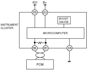
System Wiring Diagram
Operation
• The air charging pressure signal from the PCM via CAN lines is input to the microcomputer in the instrument cluster. The microcomputer outputs a control signal to the boost gauge based on the air charging pressure signal.
Boost Gauge Control
• The instrument cluster switches the boost gauge display based on the air charging pressure signal input from the PCM.
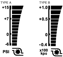
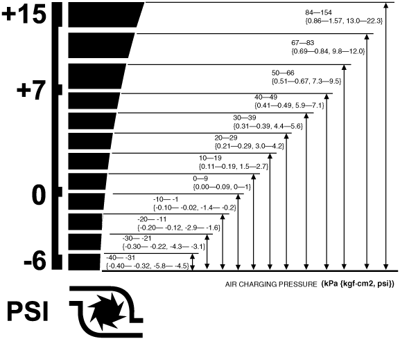
• The boost gauge has 13 display patterns that are switched according to the air charging pressure.
• When the air charging pressure value sent from the PCM is between -100 — -41, or it is abnormal, the boost gauge is not displayed.
Type A
Type B
Boost Gauge Display Switching Procedure
1. Switch the ignition to ON.
2. Press the tripmeter switch six times within 5 s.
3. ON is displayed in the odometer/tripmeter display area.
4. When the tripmeter switch is pressed while ON is displayed, OFF is displayed.
5. Press the tripmeter switch for 1 s or more while OFF is displayed.
-
• To display the boost gauge, press the tripmeter switch in Step 3 to display ON, and press the tripmeter switch for 1 s or more while ON is displayed.