 |
beltze00000109
VALVE CLEARANCE INSPECTION/ADJUSTMENT
id011000066200
VALVE CLEARANCE INSPECTION
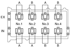
1. Turn the crankshaft clockwise so that the No.1 piston is at TDC of the compression stroke.
2. Measure the valve clearance at A in the figure.
beltze00000109
|
3. Rotate the crankshaft clockwise 360° so that the No.4 piston is at the TDC of the compression stroke.
4. Measure the valve clearance at B in the figure.
VALVE CLEARANCE ADJUSTMENT
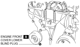
1. Remove the engine front cover lower blind plug.
beleue00000039
|
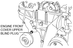
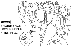
2. Remove the engine front cover upper blind plug.
beleue00000040
|
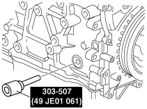
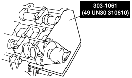
3. Remove the cylinder block lower blind plug and install the SST.
beltze00000110
|
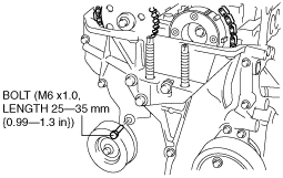
4. Rotate the crankshaft clockwise so that the No.1 piston is at TDC of the compression stroke. (The position crank weight contacts the SST.)
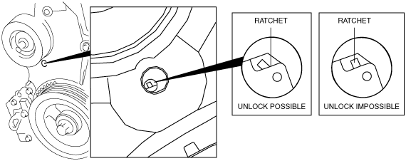
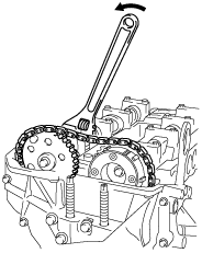
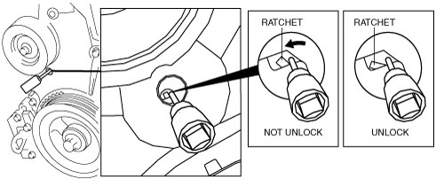
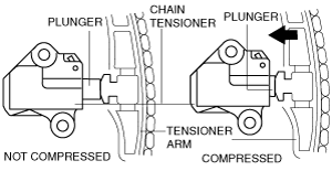
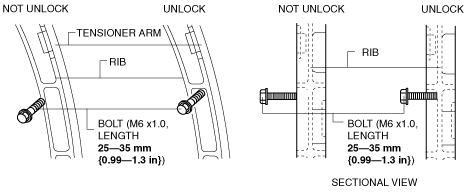
5. Loosen the timing chain using the following procedure:
Ratchet unlock position
beluce00000013
|
beltze00000112
|
am8rrw00002539
|
beltze00000124
|
am8rrw00002541
|
beltze00000114
|
beltze00000115
|
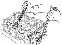
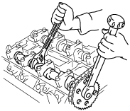
6. Secure the exhaust camshaft using a wrench on the cast hexagon and loosen the camshaft sprocket bolt.
beltze00000116
|
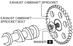
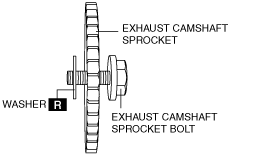
7. Remove the exhaust camshaft sprocket bolt, exhaust camshaft sprocket, and washer as a single unit.
beleue00000044
|
8. Remove the OCV.
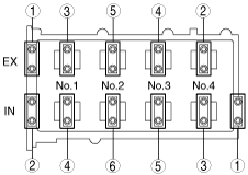
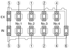
9. Loosen the camshaft cap bolts in two or three passes in the order shown in the figure, and remove the camshaft bearing caps.
beltze00000117
|
10. Remove the camshafts for intake and exhaust sides.
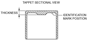
11. Remove the tappet.
12. Select and install the suitable tappet according to the result of valve clearance inspection.
beltze00000118
|
Tappet specification
|
Identification mark |
Thickness (mm {in}) |
Tolerance (mm {in}) |
|---|---|---|
|
000
|
3.000 {0.1181}
|
±0.0125 {0.000492}
|
|
025
|
3.025 {0.1191}
|
±0.0125 {0.000492}
|
|
050
|
3.050 {0.1201}
|
±0.0125 {0.000492}
|
|
075
|
3.075 {0.1211}
|
±0.0125 {0.000492}
|
|
100
|
3.100 {0.1220}
|
±0.0125 {0.000492}
|
|
122
|
3.122 {0.1229}
|
±0.0100 {0.000394}
|
|
142
|
3.142 {0.1237}
|
±0.0100 {0.000394}
|
|
162
|
3.162 {0.1245}
|
±0.0100 {0.000394}
|
|
182
|
3.182 {0.1253}
|
±0.0100 {0.000394}
|
|
202
|
3.202 {0.1261}
|
±0.0100 {0.000394}
|
|
222
|
3.222 {0.1269}
|
±0.0100 {0.000394}
|
|
242
|
3.242 {0.1276}
|
±0.0100 {0.000394}
|
|
262
|
3.262 {0.1284}
|
±0.0100 {0.000394}
|
|
282
|
3.282 {0.1292}
|
±0.0100 {0.000394}
|
|
302
|
3.302 {0.130}
|
±0.0100 {0.000394}
|
|
322
|
3.322 {0.1308}
|
±0.0100 {0.000394}
|
|
342
|
3.342 {0.1316}
|
±0.0100 {0.000394}
|
|
362
|
3.362 {0.1324}
|
±0.0100 {0.000394}
|
|
382
|
3.382 {0.1331}
|
±0.0100 {0.000394}
|
|
402
|
3.402 {0.1339}
|
±0.0100 {0.000394}
|
|
422
|
3.422 {0.1347}
|
±0.0100 {0.000394}
|
|
442
|
3.442 {0.1355}
|
±0.0100 {0.000394}
|
|
462
|
3.462 {0.1363}
|
±0.0100 {0.000394}
|
|
482
|
3.482 {0.1371}
|
±0.0100 {0.000394}
|
|
502
|
3.502 {0.1379}
|
±0.0100 {0.000394}
|
|
522
|
3.522 {0.1387}
|
±0.0100 {0.000394}
|
|
542
|
3.542 {0.1394}
|
±0.0100 {0.000394}
|
|
562
|
3.562 {0.1402}
|
±0.0100 {0.000394}
|
|
582
|
3.582 {0.1410}
|
±0.0100 {0.000394}
|
|
602
|
3.602 {0.1418}
|
±0.0100 {0.000394}
|
|
625
|
3.625 {0.1427}
|
±0.0125 {0.000492}
|
|
650
|
3.650 {0.1437}
|
±0.0125 {0.000492}
|
|
675
|
3.675 {0.1447}
|
±0.0125 {0.000492}
|
|
700
|
3.700 {0.1457}
|
±0.0125 {0.000492}
|
|
725
|
3.725 {0.1467}
|
±0.0125 {0.000492}
|
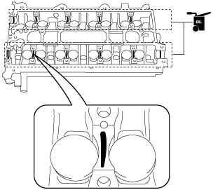
13. Apply the gear oil (SAE No. 90 or equivalent) to each journal of the cylinder head as shown in the figure.
beltze00000073
|
14. Install the camshaft with No.1 cylinder cam aligned at TDC of the compression stroke.
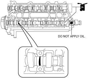
15. Apply the gear oil (SAE No. 90 or equivalent) to each journal of the camshaft as shown in the figure. However, do not apply it to the end journal of the intake camshaft.
beltze00000074
|
16. Carefully apply sealan agent (Loctite 518 or 962) to the area indicated in the figure so that it does not leak into the sliding part then, apply the gear oil (SAE No. 90 or equivalent) to the journal.
beltze00000119
|
17. Install the camshaft bearing cap and tighten the camshaft bearing cap bolts in two passes in the order shown in the figure.
beltze00000076
|
18. Install the OCV.
beltze00000120
|
19. Install the exhaust camshaft sprocket bolt, exhaust camshaft sprocket, and a new washer as a single unit.
am3zzw00004783
|
20. Install the SST on the camshaft as shown in the figure.
beltze00000121
|
21. Remove the bolt (M6 X 1.0 length 25—35 mm {0.99—1.37 in}) from the engine front cover upper blind plug and apply tension to the timing chain.
22. Rotate the crankshaft clockwise and verify that the No.1 piston is at TDC of the compression stroke.
23. Secure the exhaust camshaft using a wrench on the cast hexagon and tighten the sprocket bolt.
am8rrw00002546
|
24. Remove the SST from the camshaft.
25. Remove the SST installed in the cylinder block lower blind plug hole.
26. Rotate the crankshaft clockwise two turns and inspect the valve timing.
27. Apply silicone sealant and install the engine front cover upper blind plug.
beleue00000038
|
28. Install the cylinder block lower blind plug.
am8rrw00002588
|
29. Install a new engine front cover lower blind plug.
beleue00000039
|