 |
beltze00000027
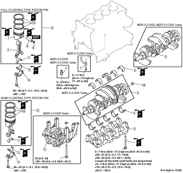
CYLINDER BLOCK ASSEMBLY (I)
id011000504000
1. Assemble in the order indicated in the table.
beltze00000027
|
|
1
|
Oil jet valve
|
|
2
|
Upper main bearing, thrust bearing
|
|
3
|
Crankshaft
|
|
4
|
Lower main bearing
|
|
5
|
Main bearing cap
|
|
6
|
Connecting rod (Full floating type piston pin)
|
|
7
|
Piston (Full floating type piston pin)
|
|
8
|
Piston pin (Full floating type piston pin)
(SeePiston Pin Assembly Note.)
|
|
9
|
Snap ring (Full floating type piston pin)
|
|
10
|
Piston ring
(See Piston Ring Assembly Note.)
|
|
11
|
Upper connecting rod bearing
|
|
12
|
Connecting rod, piston
(See Piston Assembly Note.)
|
|
13
|
Lower connecting rod bearing
|
|
14
|
Connecting rod cap
|
|
15
|
Engine balancer (MZR 2.3 DISI Turbo)
(See Balancer Unit Assembly Note.)
|
|
16
|
Pilot bearing (If equipped)
(See Pilot Bearing Assembly Note.)
|
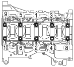
Main Bearing Cap Assembly Note
1. Tighten the crank bearing caps in the order shown in the figure.
beltze00000028
|
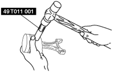
Piston Pin Assembly Note
1. Assemble the piston pin using the SST.
beltze00000069
|
beltze00000029
|
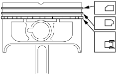
Piston Ring Assembly Note
1. Assemble the oil ring.
2. Assemble the second ring with the notch facing downward.
3. Assemble the top ring. (MZR 2.0 DISI, MZR 2.0 DISI i-stop)
4. Assemble the top ring with scraper face side upward. (MZR 2.3 DISI Turbo)
beltze00000030
|
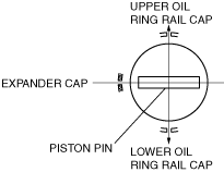
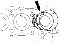
Piston Assembly Note
1. Assemble the three-piece oil ring so that the three-piece oil ring end gaps do not overlap as shown in the figure.
beltze00000128
|
2. Insert the piston into the cylinder with the arrow on top of the piston facing the front of the engine.
beltze00000032
|
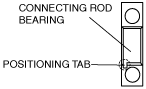
Connecting Rod Bearing Assembly Note
1. Install the connecting rod bearing to the connecting rod and connecting rod caps as shown in the figure.
beltze00000033
|
beltze00000034
|
Connecting Rod Cap Assembly Note
1. Tighten the connecting rod installation bolts using the following procedure.
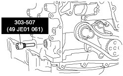
Balancer Unit Assembly Note
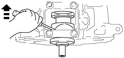
1. Visually inspect the balancer unit gear for damage and verify that the shaft rotates smoothly.
2. Remove the cylinder block lower blind plug and install the SST.
b3e0110e110
|
3. Rotate the crankshaft in the direction of engine rotation so that the No. 1 cylinder is at top dead center (TDC). (Until the counterweight contacts the SST and stops.)
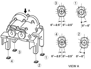
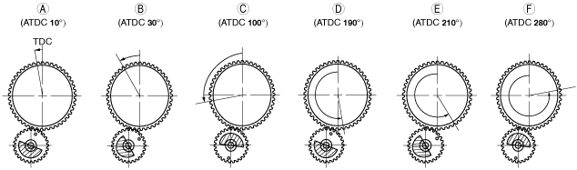
4. Assemble the master shims (No. 50) to the shim seating face of the balancer unit at the angles shown in the figure.
beltze00000035
|
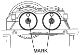
5. With the balancer unit marks at the exact top center positions, assemble the balancer unit to the cylinder block and tighten the bolts in a criss-cross pattern in two steps.
beltze00000036
|
6. Remove the SST installed in Step 2.
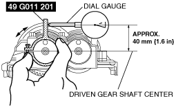
7. Measure the gear backlash using the following procedure.
beltze00000037
|
beltze00000038
|
b3e110ze4064
|
8. Select the adjustment shim from the selection table based on the measured minimum value of the backlash.
Adjustment shim selection table
|
Backlash mm {in} |
Selection shim (No.) |
Shim thickness mm {in} |
Backlash mm {in} |
Selection shim (No.) |
Shim thickness mm {in} |
|---|---|---|---|---|---|
|
0.267—0.273 {0.01051—0.01074}
|
15
|
1.15 {0.0452}
|
0.127—0.133 {0.00500—0.00523}
|
35
|
1.35 {0.0531}
|
|
0.260—0.266 {0.01023—0.01047}
|
16
|
1.16 {0.0456}
|
0.120—0.126 {0.00472—0.00496}
|
36
|
1.36 {0.0535}
|
|
0.253—0.259 {0.00996—0.01019}
|
17
|
1.17 {0.0460}
|
0.113—0.119 {0.00444—0.00468}
|
37
|
1.37 {0.0539}
|
|
0.246—0.252 {0.00968—0.00992}
|
18
|
1.18 {0.0464}
|
0.106—0.112 {0.00417—0.00440}
|
38
|
1.38{0.0543}
|
|
0.239—0.245 {0.00940—0.00964}
|
19
|
1.19 {0.0468}
|
0.099—0.105 {0.00389—0.00413}
|
39
|
1.39 {0.0547}
|
|
0.232—0.238 {0.00913—0.00937}
|
20
|
1.20 {0.0472}
|
0.092—0.098 {0.00362—0.00385}
|
40
|
1.40 {0.0551}
|
|
0.225—0.231 {0.00885—0.00909}
|
21
|
1.21 {0.0476}
|
0.085—0.091 {0.00334—0.00358}
|
41
|
1.41 {0.0555}
|
|
0.218—0.224 {0.00858—0.00881}
|
22
|
1.22 {0.0480}
|
0.078—0.084 {0.00307—0.00330}
|
42
|
1.42 {0.0559}
|
|
0.211—0.217 {0.00830—0.00854}
|
23
|
1.23 {0.0484}
|
0.071—0.077 {0.00279—0.00303}
|
43
|
1.43 {0.0562}
|
|
0.204—0.210 {0.00803—0.00826}
|
24
|
1.24 {0.0488}
|
0.064—0.070 {0.00251—0.00275}
|
44
|
1.44 {0.0566}
|
|
0.197—0.203 {0.00775—0.00799}
|
25
|
1.25 {0.492}
|
0.057—0.063 {0.00224—0.00248}
|
45
|
1.45 {0.0570}
|
|
0.190—0.196 {0.00748—0.00771}
|
26
|
1.26 {0.496}
|
0.050—0.056 {0.00196—0.00220}
|
46
|
1.46 {0.0574}
|
|
0.183—0.189 {0.00720—0.00744}
|
27
|
1.27 {0.499}
|
0.043—0.049 {0.00169—0.00192}
|
47
|
1.47 {0.0578}
|
|
0.176—0.182 {0.00692—0.00716}
|
28
|
1.28 {0.503}
|
0.036—0.042 {0.00141—0.00165}
|
48
|
1.48 {0.0582}
|
|
0.169—0.175 {0.00665—0.00688}
|
29
|
1.29 {0.507}
|
0.029—0.035 {0.00114—0.00137}
|
49
|
1.49 {0.0586}
|
|
0.162—0.168 {0.00637—0.00661}
|
30
|
1.30 {0.511}
|
0.022—0.028 {0.000866—0.00110}
|
50 (master)
|
1.50 {0.0590}
|
|
0.155—0.161 {0.00610—0.00633}
|
31
|
1.31 {0.515}
|
0.015—0.021 {0.00059—0.000826}
|
51
|
1.51 {0.0594}
|
|
0.148—0.154 {0.00582—0.00606}
|
32
|
1.32 {0.519}
|
0.008—0.014 {0.000314—0.000551}
|
52
|
1.52 {0.0598}
|
|
0.141—0.147 {0.00555—0.00578}
|
33
|
1.33 {0.523}
|
0.001—0.007 {0.00003—0.000275}
|
53
|
1.53 {0.0602}
|
|
0.134—0.140 {0.00527—0.00551}
|
34
|
1.34 {0.527}
|
0.000—0.000 {0.000—0.000}
|
54
|
1.54 {0.0606}
|
9. Verify that the No. 1 cylinder is at TDC.
10. Remove the master shim from the balancer unit and assemble the selected adjustment shim at the angles shown in the figure.
beltze00000035
|
11. Perform Steps 5—7.
12. Verify that the measured backlash is within the specified range.
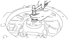
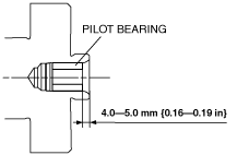
Pilot Bearing Assembly Note
1. Assemble the pilot bearing using the corresponding 20 mm {0.79 in} side of a Snap-on brand millimeter size bushing driver set A160M adapter A160M7 (20—22 mm {0.79—0.86 in}).
beltze00000039
|
c3u0510w013
|