 |
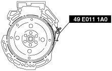
beltze00000126
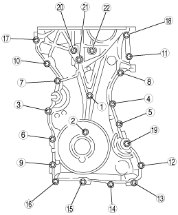
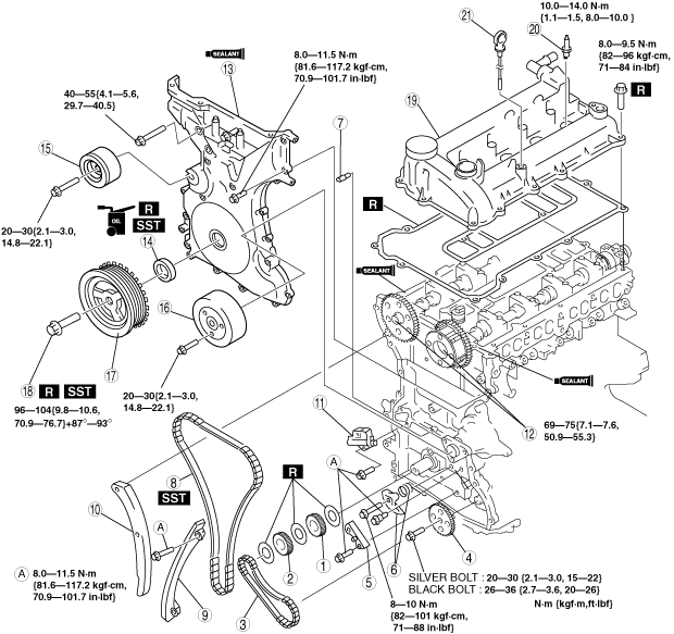
TIMING CHAIN ASSEMBLY
id011000505600
1. Assemble in the order indicated in the table.
beltze00000126
|
|
1
|
Oil pump drive sprocket
(See Drive Sprocket Assembly Note.)
|
|
2
|
Crankshaft sprocket
(See Drive Sprocket Assembly Note.)
|
|
3
|
Oil pump chain
|
|
4
|
Oil pump driven sprocket
|
|
5
|
Oil pump chain guide (MZR 2.3 DISI Turbo)
|
|
6
|
Oil pump chain tensioner
|
|
7
|
Oil jet
|
|
8
|
Timing chain
(See Timing Chain Assembly Note.)
|
|
9
|
Timing chain guide
|
|
10
|
Timing chain tensioner arm
|
|
11
|
Timing chain tensioner
|
|
12
|
Camshaft sprocket lock bolt
|
|
13
|
Engine front cover
|
|
14
|
Front oil seal
|
|
15
|
Drive belt idler pulley (MZR 2.3 DISI Turbo)
|
|
16
|
Water pump pulley
|
|
17
|
Crankshaft pulley
|
|
18
|
Crankshaft pulley lock bolt
|
|
19
|
Cylinder head cover
|
|
20
|
Spark plug
|
|
21
|
Dipstick (MZR 2.0 DISI, MZR 2.0 DISI i-stop)
|
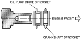
Drive Sprocket Assembly Note
1. The oil pump drive sprocket has the assembly direction as shown in the figure.
beltze00000049
|
Oil Pump Driven Sprocket Assembly Note
1. Temporarily install the crankshaft pulley and crankshaft pulley lock bolt to the crankshaft, and lock the oil pump against rotation as shown in figure.
am3uuw00001568
|
2. Install the oil pump driven sprocket, and then remove the crankshaft pulley and crankshaft pulley lock bolt.
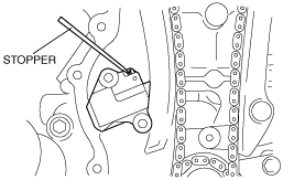
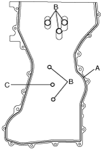
Timing Chain Assembly Note
1. Install the SST on the camshaft and align the No.1 camshaft position at TDC of the compression stroke.
beltze00000050
|
2. Remove the cylinder block lower blind plug from the cylinder block and install the SST.
am8rrw00001251
|
3. Rotate the crankshaft clockwise so that the No.1 piston is at TDC of the compression stroke. (The position crank weight contacts the SST.)
4. Install the timing chain.
5. After the chain adjuster is installed, remove the paper clip (stopper).
beltze00000051
|
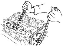
Camshaft Sprocket Lock Bolt Assembly Note
1. Lock the camshaft against rotation using a wrench on the cast hexagon.
2. Tighten the camshaft sprocket installation bolt.
beltze00000052
|
e6u110zwb047
|
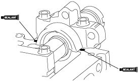
Engine Front Cover Assembly Note
1. Apply silicone sealant to the engine front cover.
beltze00000053
|
2. Tighten the engine front cover installation bolts in the order shown in the figure.
|
Installation position
|
Tightening torque N·m {kgf·m, ft·lbf}
|
|
1—18
|
8.0—11.5 N·m {81.6—117.2 kgf·cm, 70.9—101.7 in·lbf}
|
|
19—22
|
40—55 {4.1—5.6, 29.7—40.5}
|
beltze00000054
|
3. Install the oil seal using the SST.
beltze00000055
|
beltze00000056
|
Crankshaft Pulley Lock Bolt Assembly Note
1. Install the crankshaft pulley to the front cover using a bolt (M6 X 1.0). Temporarily tighten the bolt.
beltze00000057
|
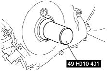
2. Use the SST to lock the crankshaft against rotation.
e6u110zeb039
|
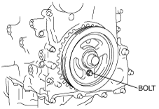
3. Tighten the pulley lock bolt.
e6u110zeb038
|
4. Remove the SST from the camshaft, and remove the bolt from the crankshaft pulley.
5. Remove the SST from the cylinder block lower blind plug, and install the cylinder block lower blind plug.
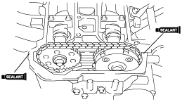
Cylinder Head Cover Assembly Note
1. Apply silicone sealant to the areas shown in the figure.
beltze00000058
|
beltze00000059
|
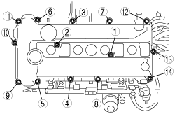
2. Install the cylinder head cover installation bolts in the order shown in the figure.
beltze00000060
|