 |
baf4za00000137
AUTOMATIC TRANSAXLE DISASSEMBLY
id051700502100
Precaution
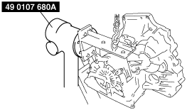
General notes
Disassembly
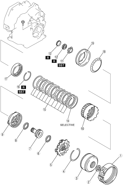
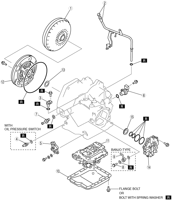
Components
baf4za00000137
|
|
1
|
Torque converter
|
|
2
|
Oil dipstick and oil filler tube
|
|
3
|
Input/turbine speed sensor
|
|
4
|
Oil pressure switch
|
|
5
|
Transaxle range switch
|
|
6
|
Vehicle speed sensor
|
|
7
|
Connector pipe
|
|
8
|
Connector bolt
|
|
9
|
Oil pipe
|
|
10
|
Oil pan
|
|
11
|
Control valve body component
|
|
12
|
Oil pump
|
|
13
|
Thrust washer
|
|
14
|
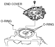
End cover
|
|
15
|
Needle bearing
|
baf4za00000002
|
|
1
|
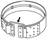
2–4 brake band
|
|
2
|
Needle bearing
|
|
3
|
Clutch component
|
|
4
|
Snap ring
|
|
5
|
Rear planetary gear component
|
|
6
|
Needle bearing
|
|
7
|
Front sun gear
|
|
8
|
Needle bearing
|
|
9
|
Front planetary gear component
|
|
10
|
Front internal gear and one-way clutch
|
|
11
|
Lock nut
|
|
12
|
Bearing
|
|
13
|
Distance piece
|
|
14
|
Snap ring
|
|
15
|
Low and reverse brake
|
|
16
|
Snap ring
|
|
17
|
One-way clutch inner race
|
|
18
|
Piston return spring
|
|
19
|
Low and reverse brake piston
|
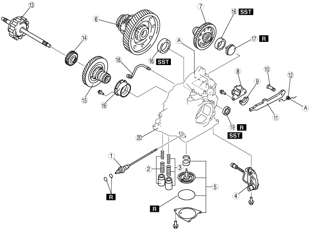
baf4za00000003
|
|
1
|
Manual shaft
|
|
2
|
Servo apply accumulator
|
|
3
|
Forward accumulator
|
|
4
|
Parking rod lever component
|
|
5
|
Band servo
|
|
6
|
Differential
|
|
7
|
Secondary gear and output gear
|
|
8
|
Actuator plate
|
|
9
|
Support actuator
|
|
10
|
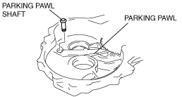
Parking pawl shaft
|
|
11
|
Parking pawl
|
|
12
|
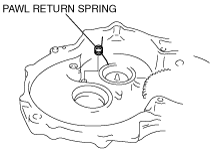
Pawl return spring
|
|
13
|
Forward clutch
|
|
14
|
Forward clutch hub
|
|
15
|
Primary gear
|
|
16
|
Bearing race
|
|
17
|
Funnel
|
|
18
|
Oil pipe
|
|
19
|
Oil seal
|
|
20
|
Transaxle case
|
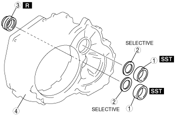
baf4za00000004
|
|
1
|
Bearing race
|
|
2
|
Adjustment shim
|
|
3
|
Oil seal
|
|
4
|
Converter housing
|
Disassembly procedure
1. Remove the torque converter, and immediately turn it so that the hole faces upward.
This will help to keep any remaining fluid from spilling.
2. Remove the ATF dipstick and oil filler tube.
3. Remove the O-ring from the oil filler tube.
4. Remove the breather hose.
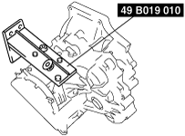
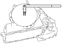
5. Assemble the SST.
baf4za00000005
|
6. Lift the transaxle and mount it on the SST.
baf4za00000006
|
7. Remove the input/turbine speed sensor.
8. Remove the O-ring from the input/turbine speed sensor.
9. Remove the oil pressure switch. (with oil pressure switch)
10. Remove the transaxle range switch.
11. Remove the vehicle speed sensor.
12. Remove the O-ring from the vehicle speedometer sensor.
13. Remove the connector pipe, connector bolt and oil pipe.
14. Remove the oil pan.
Examine any material found in the pan or on the magnet to determine the condition of the transaxle. If large amounts of material are found, replace the torque converter and carefully inspect the transaxle for the cause.
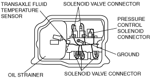
15. Disconnect the solenoid valve connector, ground, and transaxle fluid temperature sensor.
baf4za00000007
|
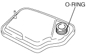
16. Remove the oil strainer.
17. Remove the O-ring from the oil strainer.
baf4za00000008
|
18. Remove the bolts as shown in the figure.
baf4za00000009
|
19. Remove the control valve body.
baf4za00000010
|
20. Remove the coupler component.
baf4za00000011
|
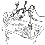
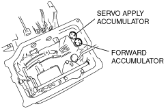
21. Remove the accumulator component.
baf4za00000012
|
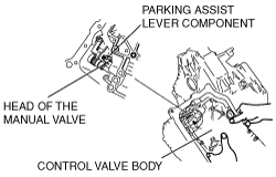
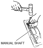
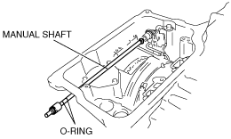
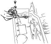
22. Remove the manual shaft.
baf4za00000013
|
baf4za00000014
|
23. Remove the parking rod lever component.
baf4za00000015
|
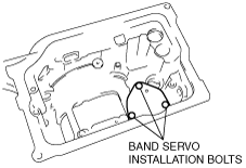
24. Remove the band servo component.
baf4za00000016
|
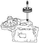
25. Remove the oil pump.
baf4za00000017
|
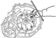
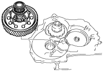
26. Remove the converter housing by tapping lightly with a plastic hammer.
baf4za00000018
|
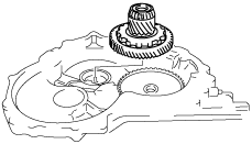
27. Remove the forward clutch component.
baf4za00000019
|
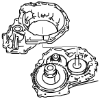
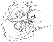
28. Remove the differential.
baf4za00000020
|
29. Remove the secondary gear and output gear.
baf4za00000021
|
30. Remove the actuator plate.
baf4za00000022
|
31. Remove the support actuator.
baf4za00000023
|
32. Pull out the parking pawl shaft.
baf4za00000024
|
33. Remove the parking pawl.
34. Remove the pawl return spring.
baf4za00000025
|
35. Remove the end cover.
36. Remove the O-ring from the transaxle case.
baf4za00000026
|
37. Remove the band strut.
baf4za00000027
|
38. Remove the 2–4 brake band, and hold it together using a piece of wire as shown in the figure.
baf4za00000028
|
39. Remove the clutch component.
baf4za00000029
|
40. Remove the snap ring.
baf4za00000030
|
41. Remove the rear planetary gear component.
baf4za00000031
|
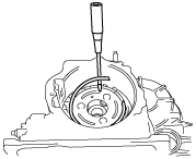
42. Remove the front sun gear by tapping its end with a flathead screwdriver or similar tool. as shown in the figure.
baf4za00000032
|
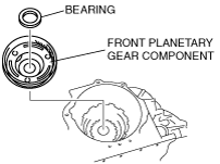
43. Remove the forward clutch hub.
44. Remove the front planetary gear component.
baf4za00000033
|
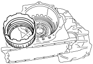
45. Remove the front internal gear and one-way clutch component.
baf4za00000034
|
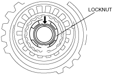
46. Remove the locknut.
baf4za00000035
|
baf4za00000036
|
baf4za00000037
|
baf4za00000038
|
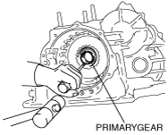
47. Remove the primary gear by tapping it with a flathead screwdriver, etc. as shown in the figure.
baf4za00000039
|
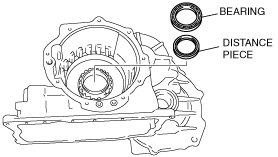
48. Remove the bearing and distance piece.
baf4za00000040
|
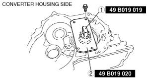
49. Remove torx screws from the converter housing side.
baf4za00000041
|
50. Remove the bearing race.
51. Remove the bearing race using the SST as shown in the figure.
baf4za00000042
|
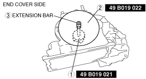
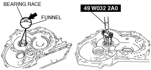
52. Tap the funnel at the areas indicated in the figure using a flathead screwdriver, etc. to make gaps big enough to install the SST. Then remove the bearing race.
baf4za00000043
|
53. Remove the funnel.
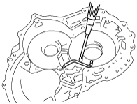
54. Remove the oil pipe.
baf4za00000044
|