 |
d6e517za5080
AUTOMATIC TRANSAXLE ASSEMBLY
d6e051700000a03
Precaution
General notes
1. Select the adjustment shims, referring to Bearing Preload.
2. If the drive plates or 2‐4 brake band are replaced with new ones, soak the new part in ATF for at least two hours before installation.
3. Before assembly, apply ATF to all seal rings, rotating parts, O‐rings, and sliding parts.
4. All O‐rings, seals, and gaskets must be replaced with the new ones included in the overhaul kit.
5. Use petroleum jelly, not grease, when assembling again.
6. When it is necessary to replace a bushing, replace the subassembly that includes that bushing.
7. Assemble the housing within 10 minutes after applying sealant, and allow it to cure for at least 30 minutes after assembly before filling the transaxle with ATF.
Assembly
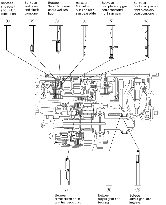
Bearing and race locations
d6e517za5080
|
Outer diameter of bearing and race
|
|
1 |
2 |
3 |
4 |
5 |
6 |
7 |
8 |
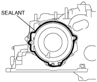
9 |
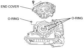
|---|---|---|---|---|---|---|---|---|---|
|
Bearing
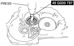
(mm {in})
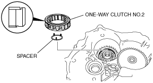
|
—
|
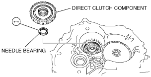
40.0 {1.57}
|
39.0 {1.54}
|
78.2 {3.08}
|
52.0 {2.05}
|
50.0 {1.97}
|
46.5 {1.83}
|
—
|
61.0 {2.40}
|
|
Race
(mm {in})
|
40.2 {1.58}
|
—
|
—
|
—
|
—
|
—
|
—
|
59.0 {2.32}
|
—
|
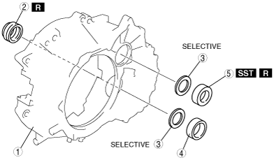
Components
d6e517za5081
|
|
1
|
Converter housing
|
|
2
|
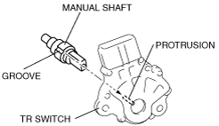
Oil seal
|
|
3
|
Adjustment shim
|
|
4
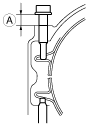
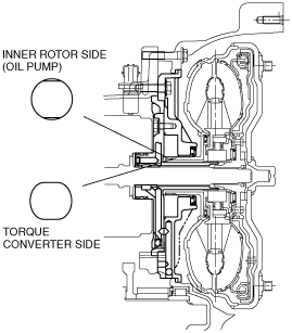
|
Bearing race
|
|
5
|
Bearing
|
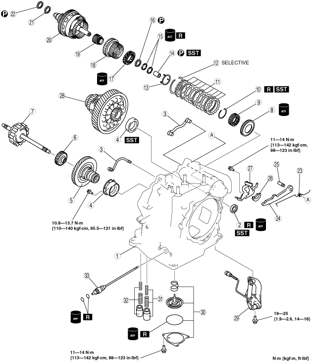
d6e517za5082
|
|
1
|
Transaxle case
|
|
2
|
Oil seal
|
|
3
|
Oil pipe
|
|
4
|
Bearing race
|
|
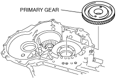
5
|
Primary gear
|
|
6
|
Forward clutch hub
|
|
7
|
Forward clutch
|
|
8
|
Reduction brake piston
|
|
9
|
Springs and retainer component
|
|
10
|
Snap ring
|
|
11
|
Reduction brake
|
|
12
|
Snap ring
|
|
13
|
Spacer
|
|
14
|
Needle bearing
|
|
15
|
Seal rings
|
|
16
|
Needle bearing
|
|
17
|
One-way clutch No.2
|
|
18
|
Direct clutch component
|
|
19
|
Secondary sun gear
|
|
20
|
Output gear component
|
|
21
|
Bearing race
|
|
22
|
Needle bearing
|
|
23
|
Pawl return spring
|
|
24
|
Parking pawl
|
|
25
|
Parking pawl shaft
|
|
26
|
Support actuator
|
|
27
|
Actuator plate
|
|
28
|
Differential
|
|
29
|
Parking rod lever component
|
|
30
|
Band servo
|
|
31
|
Forward accumulator
|
|
32
|
Servo apply accumulator
|
|
33
|
Manual shaft
|
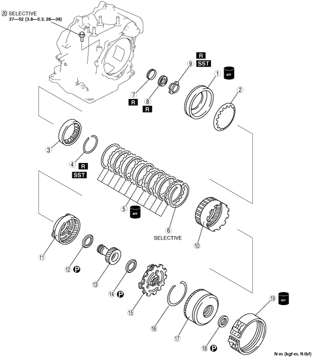
d6e517za5083
|
|
1
|
Low and reverse brake piston
|
|
2
|
Low and reverse brake return spring
|
|
3
|
One-way clutch inner race
|
|
4
|
Snap ring
|
|
5
|
Low and reverse brake
|
|
6
|
Snap ring
|
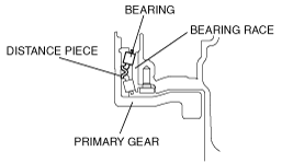
|
7
|
Distance piece
|
|
8
|
Bearing
|
|
9
|
Lock nut
|
|
10
|
Front internal gear and one-way clutch No.1
|
|
11
|
Front planetary gear component
|
|
12
|
Needle bearing
|
|
13
|
Front sun gear
|
|
14
|
Needle bearing
|
|
15
|
Rear planetary gear component
|
|
16
|
Snap ring
|
|
17
|
Clutch component
|
|
18
|
Needle bearing
|
|
19
|
2–4 brake band
|
|
20
|
Band strut
|
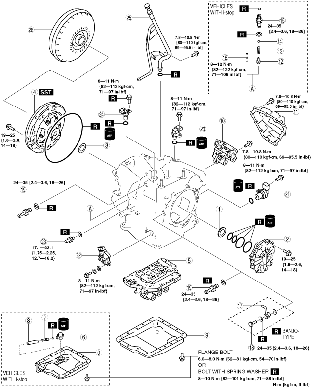
E6U517SI5002
|
|
1
|
Bearing race
|
|
2
|
End cover
|
|
3
|
Thrust washer
|
|
4
|
Oil pump
|
|
5
|
Primary control valve body
|
|
6
|
Joint
|
|
7
|
Joint pipe
|
|
8
|
Hose
|
|
9
|
Oil pan
|
|
10
|
Secondary control valve body
|
|
11
|
Oil cover
|
|
12
|
Plug
|
|
13
|
Spring
|
|
14
|
Steel ball
|
|
15
|
Connector bolt
|
|
16
|
Stud bolt
|
|
17
|
Oil pipe
|
|
18
|
Connector bolt
|
|
19
|
Connector pipe
|
|
20
|
Intermediate sensor
|
|
21
|
Vehicle speed sensor
|
|
22
|
Transaxle range switch
|
|
23
|
Oil pressure switch
|
|
24
|
Input/turbine speed sensor
|
|
25
|
Oil filler tube and oil dipstick
|
|
26
|
Torque converter
|
Assembly procedure
1. Measure the bushing of the front sun gear.
b3e0517a284
|
2. If not as specified, replace the front sun gear.
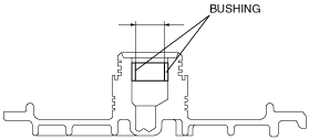
3. Measure the bushing of the end cover.
b3e0517a332
|
4. If not as specified, replace the end cover.
5. Measure the bushing of the secondary sun gear.
d6e517za5085
|
6. If not as specified, replace the secondary sun gear.
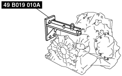
7. Assemble the SST.
d6j517za4130
|
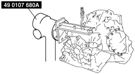
8. Lift the transaxle case and mount it on the SST.
d6j517za4131
|
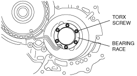
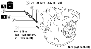
9. Install the oil pipe.
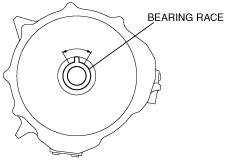
10. Install the bearing race, then tighten torx screws.
d6e517za5086
|
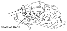
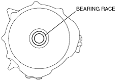
11. Install the bearing race to the transaxle case.
d6e517za5087
|
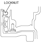
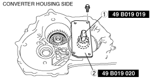
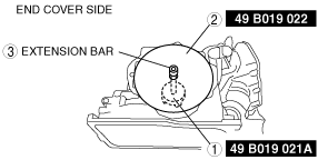
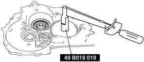
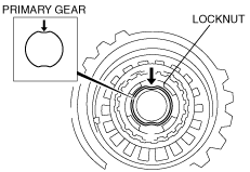
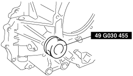
12. Install the locknut.
d6e517za5088
|
b3e0517a289
|
b3e0517a290
|
d6e517za5026
|
d6e517za5027
|
d6j517za4077
|
b3e0517a292
|
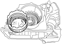
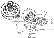
13. Install the front internal gear and one-way clutch.
d6j517za4028
|
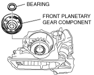
14. Apply petroleum jelly to the bearing, and secure it to the front planetary gear component.
15. Install the front planetary gear component.
d6e517za5025
|
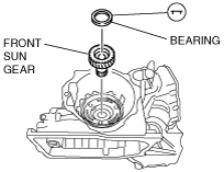
16. Apply petroleum jelly to the bearing, and secure it to the front sun gear.
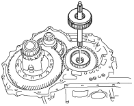
17. Install the front sun gear.
d6e517za5089
|
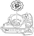
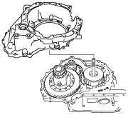
18. Install the rear planetary gear.
d6j517za4025
|
b3e0517a294
|
19. Install the snap ring.
d6j517za4075
|
20. Rotate the engine stand so that the end cover faces upward, and verify that the snap ring is installed accurately.
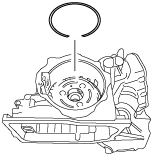
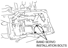
21. Install the band servo component.
d6e517za5014
|
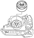
22. Apply petroleum jelly to the bearing, and secure it to the clutch component.
23. Install the clutch component.
d6j517za4023
|
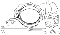
24. Install the 2-4 brake band.
d6j517za4066
|
25. Select the band strut.
b3e0517a297
|
b3e0517a298
|
Band strut length for 2-4 brake band servo stroke (mm {in})
|
36.0 {1.417}
|
36.5 {1.437}
|
37.0 {1.457}
|
|
37.25 {1.467}
|
37.5 {1.476}
|
37.75 {1.486}
|
|
38.0 {1.496}
|
38.25 {1.506}
|
38.5 {1.516}
|
|
39.0 {1.535}
|
–
|
–
|
d6e517za5023
|
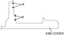
26. Use the following procedure to adjust the total end play.
b3e0517a299
|
Bearing race sizes
|
1.8 {0.071}
|
2.0 {0.079}
|
2.2 {0.087}
|
|
2.4 {0.094}
|
2.6 {0.102}
|
–
|
A-type
baf4za00000077
|
B-type
baf4za00000114
|
27. Apply ATF to new seal ring, and install it to the end cover.
b3e0517a301
|
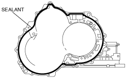
28. Apply a light coat of silicone sealant (TB1217E or equivalent) to the contact surfaces of the transaxle case and the end cover.
d6e517za5091
|
29. Apply ATF to the O-ring and install it to the transaxle case.
30. Install the end cover to the transaxle case.
d6e517za5022
|
31. Install the reduction brake to the transaxle case. (See REDUCTION BRAKE DISASSEMBLY/ASSEMBLY.)
32. Install the needle bearing using the SST as shown in the figure.
d6e517za5092
|
33. Install the spacer and one-way clutch No.2 to the transaxle case.
d6e517za5093
|
34. Apply ATF to new seal ring, and install it to the transaxle case.
35. Apply petroleum jelly to the needle bearing, and secure it to the transaxle case.
36. Install the direct clutch component to the transaxle case.
d6e517za5094
|
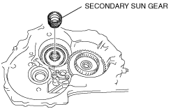
37. Install the secondary sun gear.
d6e517za5019
|
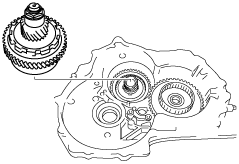
38. Install the output gear component.
d6j517za4039
|
39. Install the bearing race to the output gear component.
40. Apply petroleum jelly to the needle bearing, and secure it to the output gear component.
41. Use the following procedure to adjust the total end play.
d6e517za5095
|
Adjust shim size for output gear component total end play
|
total end play {in} |
Adjust shims sizes mm {in} |
|---|---|
|
1.431—1.481 {0.057—0.058}
|
1.20 {0.047}
|
|
1.381—1.431 {0.055—0.056}
|
1.15 {0.045}
|
|
1.331—1.381 {0.053—0.054}
|
1.10 {0.043}
|
|
1.281—1.331 {0.051—0.052}
|
1.05 {0.041}
|
|
1.231—1.281 {0.049—0.050}
|
1.00 {0.039}
|
|
1.181—1.231 {0.047—0.048}
|
0.95 {0.037}
|
|
1.131—1.181 {0.045—0.046}
|
0.90 {0.035}
|
|
1.081—1.131 {0.043—0.044}
|
0.85 {0.033}
|
|
1.031—1.081 {0.041—0.042}
|
0.80 {0.031}
|
|
0.981—1.031 {0.039—0.040}
|
0.75 {0.029}
|
|
0.931—0.981 {0.037—0.038}
|
0.70 {0.028}
|
|
0.881—0.931 {0.035—0.036}
|
0.65 {0.026}
|
|
0.831—0.881 {0.033—0.034}
|
0.60 {0.024}
|
|
0.781—0.831 {0.031—0.032}
|
0.55 {0.022}
|
|
0.731—0.781 {0.029—0.030}
|
0.50 {0.020}
|
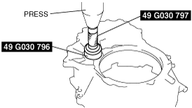
42. Install the bearing using the SST as shown in the figure.
d6e517za5096
|
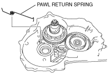
43. Install the pawl return spring to the transaxle case.
d6e517za5018
|
44. Install the packing pawl and parking pawl shaft to the transaxle case.
d6e517za5017
|
45. Install the pawl return spring to the parking pawl and parking pawl shaft.
d6e517za5097
|
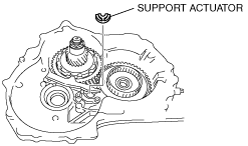
46. Install the support plate to the transaxle case.
d6e517za5016
|
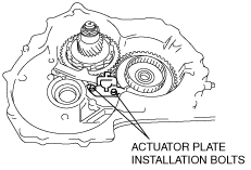
47. Install the actuator plate to the transaxle case.
d6e517za5015
|
48. Install the differential.
d6j517za4017
|
49. Install the forward clutch hub.
50. Install the forward clutch component.
d6j517za4016
|
51. Apply a light coat of silicone sealant (TB1217E or equivalent) to the contact surfaces of the converter housing and the transaxle case.
b3e0517a305
|
52. Install the converter housing.
d6j517za4015
|
53. Install the SST into the differential side gears.
d6j517za4070
|
54. Apply ATF to the new O-ring and install it to the oil pump.
55. Install the oil pump.
d6j517za4014
|
56. Install the parking rod lever component.
d6j517za4012
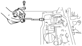
|
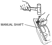
57. Apply ATF to the new O-ring and install it to the manual shaft.
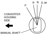
58. Install the manual shaft.
d6e517za5013
|
d6e517za5012
|
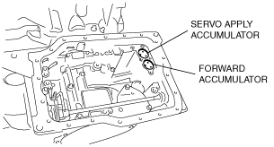
59. Install the accumulator component.
d6e517za5011
|
60. Install the coupler component.
d6j517za4008
|
d6e517za5002
|
61. Install the primary control valve body.
d6e517za5098
|
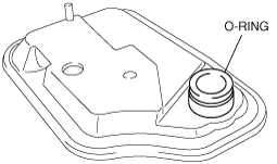
62. Apply ATF to the new O-ring and install it to the oil strainer.
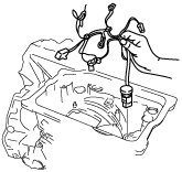
63. Install the oil strainer.
d6e517za5099
|
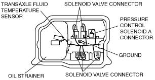
64. Match the harness colors, then connect the solenoid connector and transaxle fluid temperature sensor.
|
Solenoid valve |
Color of connector (harness side) |
|---|---|
|
Pressure control solenoid A
|
Black
|
|
Shift solenoid A
|
White
|
|
Shift solenoid B
|
Blue
|
|
Shift solenoid C
|
Green
|
|
Shift solenoid D
|
White
|
|
Shift solenoid E
|
Black
|
65. Install the ground.
d6e517za5010
|
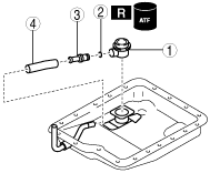
66. Install in the order shown in the figure. (vehicles with i-stop)
EZE517ZSI005
|
|
1
|
Joint
|
|
2
|
O-ring
|
|
3
|
Joint pipe
|
|
4
|
Hose
|
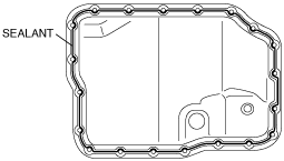
67. Apply a light coat of silicone sealant (TB1217E or equivalent) to the contact surfaces of oil pan and transaxle case.
d6e517za5100
|
68. Install the oil pan before the applied sealant starts to harden.
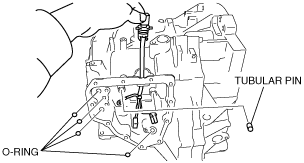
69. Apply ATF to the new O-ring and install it to the transaxle case.
70. Install the tubular pins.
d6e517za5009
|
71. Install the coupler component.
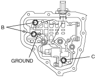
72. Install the secondary control valve body and ground.
d6e517za5102
|
73. Match the harness colors, then connect the solenoid connector.
|
Solenoid valve |
Color of connector (harness side) |
|---|---|
|
Pressure control solenoid B
|
Green
|
|
Shift solenoid F
|
Black
|
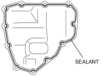
74. Apply a light coat of silicone sealant (TB1217E or equivalent) to the contact surfaces of oil cover and transaxle case.
d6e517za5101
|
75. Install the oil cover before the applied sealant starts to harden.
76. Install in the order shown in the figure. (vehicles with i-stop)
EZE517ZSI006
|
|
1
|
Plug
|
|
2
|
Spring
|
|
3
|
Steel ball
|
|
4
|
Packing
|
|
5
|
Connector bolt
|
|
6
|
O-ring
|
|
7
|
Stud bolt
|
77. Install the connector pipe.
78. Apply ATF to the new O-ring and install it to the intermediate sensor.
79. Install the intermediate sensor.
80. Apply ATF to the new O-ring and install it to the vehicle speed sensor.
81. Install the vehicle speed sensor.
82. Apply ATF to the new O-ring and install it to the input/turbine speed sensor.
83. Install the oil pressure switch.
84. Install the input/turbine speed sensor using a new bolt.
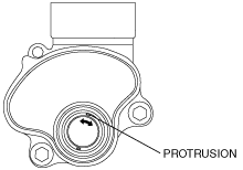
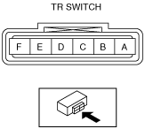
85. Install the transaxle range switch.
d6e517aw5007
|
b3e0517a315
|
b3e0517a316
|
b3e0517a317
|
b3e0517a316
|
b3e0517a318
|
b3e0517a319
|
86. Remove the transaxle from the SST.
87. Apply ATF to the new O-ring and install it to the oil filler tube.
88. Install the oil dipstick and oil filler tube to the transaxle.
89. Drain any ATF remaining in the torque converter.
90. Pour in solvent (approx. 0.5 L {0.53 US qt, 0.44 lmp qt}),
91. Shake the torque converter to clean the inside.
92. Pour out the solvent.
93. Pour the ATF.
94. Install the torque converter by aligning its gap to the oil pump inner rotor gap as shown in the figure.
d6e517za5103
|
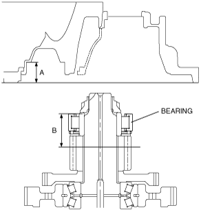
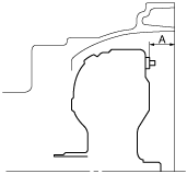
95. To ensure that the torque converter is installed accurately, measure distance A between the end of the torque converter and the end of the converter housing.
b3e0517a321
|