SECONDARY CONTROL VALVE BODY DISASSEMBLY/ASSEMBLY
D6E051721100A02
Secondary Control Valve Body Disassembly
-
Caution
-
• Denting or scratching these components will reduce the ability of the transaxle to shift properly. When handling these components or the valve body that contains them, be careful not to drop or hit them.
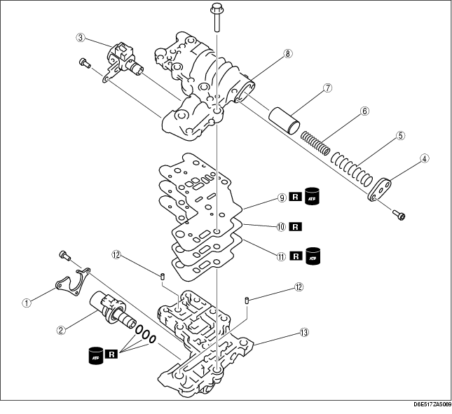
1. Disassemble in the order indicated in the table.
2. Neatly arrange the removed parts to avoid confusing the similar parts.
-
Warning
-
• Using compressed air can cause dirt and other particles to fly out, causing injury to the eyes. Wear protective eye wear whenever using compressed air.
3. Clean the removed parts with cleaning solvent, then use compressed air to dry them. Use compressed air to clean out all holes and passages.
|
1
|
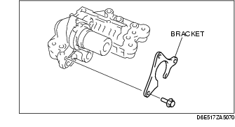
Bracket
|
|
2
|
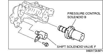
Pressure control solenoid B
|
|
3
|
Shift solenoid F
|
|
4
|
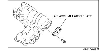
4/5 accumulator plate
|
|
5
|
4/5 accumulator large spring
|
|
6
|
4/5 accumulator small spring
|
|
7
|
4/5 accumulator
|
|
8
|
Secondary lower control valve body
|
|
9
|
Gasket G
|
|
10
|
Separator plate
|
|
11
|
Gasket H
|
|
12
|
Tubular pin
|
|
13
|
Secondary main control valve body
|
Disassembly procedure
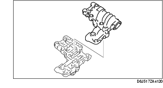
1. Remove the bracket.
2. Remove the pressure control solenoid B and shift solenoid F.
3. Remove the 4/5 accumulator plate.
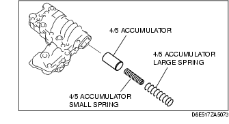
4. Remove the 4/5 accumulator large spring, 4/5 accumulator small spring and 4/5 accumulator.
5. Loosen the bolts evenly in the pattern shown.
6. Remove the secondary lower control valve body.
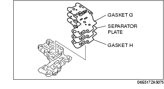
7. Remove the gasket G, separator plate and gasket H.
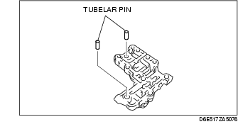
8. Remove the tubular pins.
Secondary Main Control Valve Body Disassembly/Assembly
-
Caution
-
• Denting or scratching these precisely machined components will reduce the ability of the transaxle to shift properly. When handling these components or the valve body that contains them be careful not to drop or hit them.
-
Note
-
• If a valve does not slide out under its own weight, place the valve body open-side down and tap on the valve body lightly with a plastic hammer.
1. Disassemble in the order indicated in the table.
-
Warning
-
• Using compressed air can cause dirt and other particles to fly out, causing injury to the eyes. Wear protective eye wear whenever using compressed air.
2. Clean all parts and holes using compressed air and apply ATF to them immediately before assembly.
3. Assemble in the reverse order of disassembly.

|
1
|
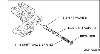
Retainer
|
|
2
|
4-5 shift valve spring
|
|
3
|
4-5 shift valve A
|
|
4
|
4-5 shift valve B
|
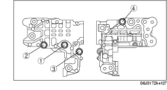
Assembly procedure
1. Measure the spring free length.
Secondary control valve body spring (standard)
|
Item
|
Outer diameter
mm {in}
|
Free length
mm {in}
|
No. of coils
|
Wire diameter
mm {in}
|
|
4-5 shift valve spring
|
8.7 {0.343}
|
27.0 {1.063}
|
10.7
|
0.8 {0.031}
|
-
• If not as specified, replace the springs.
2. Install the 4-5 shift valve B, 4-5 shift valve A, 4-5 shift valve spring and retainer.
Secondary Control Valve Body Assembly
1. Verify that all parts are clean and free of dust and other small particles.
2. Apply ATF to all parts.
3. Assemble in the reverse order of disassembly.
|
1
|
Secondary main control valve body
|
|
2
|
Tubular pin
|
|
3
|
Gasket H
|
|
4
|
Separator plate
|
|
5
|
Gasket G
|
|
6
|
Secondary lower control valve body
|
|
7
|
4/5 accumulator
|
|
8
|
4/5 accumulator small spring
|
|
9
|
4/5 accumulator large spring
|
|
10
|
4/5 accumulator plate
|
|
11
|
Shift solenoid F
|
|
12
|
Pressure control solenoid B
|
|
13
|
Bracket
|
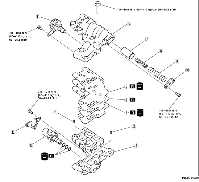
Assembly procedure
1. Install the tubular pins into the secondary main control valve body.
-
Caution
-
• Do not confuse gaskets G and H.
2. Set the new gasket H, separator plate, and new gasket G on the secondary main control valve body.
3. Set the secondary lower control valve body onto the secondary main control valve body.
4. Tighten the bolts evenly and gradually in the order shown.
Tightening torque
-
7.8-10.8 N·m
-
{80-110 kgf·cm, 69-95.5 in·lbf}
5. Measure the spring free length.
Secondary control valve body spring (standard)
|
Item
|
Outer diameter
mm {in}
|
Free length
mm {in}
|
No. of coils
|
Wire diameter
mm {in}
|
|
4/5 accumulator large spring
|
21.2 {0.835}
|
72.2 {2.843}
|
14.0
|
2.6 {0.102}
|
|
4/5 accumulator small spring
|
15.2 {0.598}
|
53.7 {2.114}
|
11.9
|
3.2 {0.126}
|
-
• If not as specified, replace the springs.
6. Install the 4/5 accumulator, 4/5 accumulator small spring and 4/5 accumulator large spring.
7. Install the 4/5 accumulator plate.
Tightening torque
-
7.8-10.8 N·m
-
{80-110 kgf·cm, 69-95.5 in·lbf}
8. Install the shift solenoid F and pressure control solenoid B.
Tightening torque
-
7.8-10.8 N·m
-
{80-110 kgf·cm, 69-95.5 in·lbf}
9. Install the bracket.
Tightening torque
-
7.8-10.8 N·m
-
{80-110 kgf·cm, 69-95.5 in·lbf}