 |
am3zzn00000281
DIAGNOSTIC TEST MODE[ZJ, ZY, Z6]
id0102c1100200
|
Diagnostic test mode |
Item |
|---|---|
|
Mode 01
|
Sending diagnostic data (PID data monitor/On-board system readiness test)
|
|
Mode 02
|
Sending freeze frame data
|
|
Mode 03
|
Sending emission-related malfunction code (DTC)
|
|
Mode 04
|
Clearing/resetting emission-related malfunction information
|
|
Mode 06
|
Sending intermittent monitoring system test results (DMTR)
|
|
Mode 07
|
Sending continuous monitoring system test results (pending code)
|
|
Mode 09
|
Request vehicle information
|
Sending Diagnostic Data
PID data monitor
PID data monitor table
|
Full names |
Unit |
|
|---|---|---|
|
Fuel system loop status
|
Refer to list below.
|
|
|
LOAD
|
%
|
|
|
ECT
|
°C
|
°F
|
|
Short term fuel trim
|
%
|
|
|
Long term fuel trim
|
%
|
|
|
Engine speed
|
rpm
|
|
|
Vehicle speed
|
km/h
|
mph
|
|
Spark advance
|
°
|
|
|
IAT
|
°C
|
°F
|
|
MAF
|
g/s
|
|
|
Absolute TP
|
%
|
|
|
O2S location
|
No unit
|
|
|
Input voltage from front HO2S
|
V
|
|
|
Short term fuel trim associated with front HO2S
|
%
|
|
|
Input voltage from rear HO2S
|
V
|
|
|
Short term fuel trim associated with rear HO2S
|
%
|
|
|
OBD requirement according to vehicle design
|
No unit
|
|
|
Time since engine start
|
s
|
|
|
Distance travelled while MIL is activated
|
km
|
miles
|
|
Purge solenoid valve control signal
|
%
|
|
|
Number of warm‐ups since DTCs cleared
|
No unit
|
|
|
Distance travelled since DTCs cleared
|
km
|
miles
|
|
BARO*1
|
kPa
|
|
|
Estimated catalyst converter temperature
|
°C
|
°F
|
|
PCM voltage
|
V
|
|
|
Absolute load value
|
%
|
|
|
Theoretical air/fuel ratio coefficient to calculate target air/fuel ratio
|
No unit
|
|
|
Relative TP
|
%
|
|
On-board system readiness test
Sending Freeze Frame Data
Freeze frame data monitor table
|
Full names |
Unit |
|
|---|---|---|
|
DTC that caused required Freeze Frame Data storage
|
No unit
|
|
|
Fuel system loop status
|
Refer to list below.
|
|
|
LOAD
|
%
|
|
|
ECT
|
°C
|
°F
|
|
Short term fuel trim
|
%
|
|
|
Long term fuel trim
|
%
|
|
|
Engine speed
|
rpm
|
|
|
Vehicle speed
|
km/h
|
mph
|
|
Spark advance
|
°
|
|
|
IAT
|
°C
|
°F
|
|
MAF
|
g/s
|
|
|
Absolute TP
|
%
|
|
|
Time since engine start
|
s
|
|
|
Purge solenoid valve control signal
|
%
|
|
|
Number of warm‐ups since DTCs cleared
|
No unit
|
|
|
Distance travelled since DTCs cleared
|
km
|
miles
|
|
BARO*1
|
kPa
|
|
|
Estimated catalyst converter temperature
|
°C
|
°F
|
|
PCM voltage
|
V
|
|
|
Absolute load value
|
%
|
|
|
Theoretical air/fuel ratio coefficient to calculate target air/fuel ratio
|
No unit
|
|
|
Relative TP
|
%
|
|
Sending Emission-related Malfunction Code
Without throttle valve actuator
|
DTC No. |
Condition |
MIL |
DC |
Monitor item |
Self-test type*1 |
Memory function |
|---|---|---|---|---|---|---|
|
P0011
|
CMP-timing over-advanced
|
ON
|
1
|
CCM
|
C, R
|
×
|
|
P0012
|
CMP-timing over-retarded
|
ON
|
2
|
CCM
|
C, R
|
×
|
|
P0031
|
Front HO2S heater control circuit low
|
ON
|
2
|
HO2S heater
|
C, O, R
|
×
|
|
P0032
|
Front HO2S heater control circuit high
|
ON
|
2
|
HO2S heater
|
C, O, R
|
×
|
|
P0037
|
Rear HO2S heater control circuit low
|
ON
|
2
|
HO2S heater
|
C, O, R
|
×
|
|
P0038
|
Rear HO2S heater control circuit high
|
ON
|
2
|
HO2S heater
|
C, O, R
|
×
|
|
P0101
|
MAF sensor circuit range/performance problem
|
ON
|
2
|
CCM
|
C
|
×
|
|
P0102
|
MAF sensor circuit low input
|
ON
|
1
|
CCM
|
C, O, R
|
×
|
|
P0103
|
MAF sensor circuit high input
|
ON
|
1
|
CCM
|
C, O, R
|
×
|
|
P0111
|
IAT sensor circuit range/performance problem
|
ON
|
2
|
CCM
|
C
|
×
|
|
P0112
|
IAT sensor circuit low input
|
ON
|
1
|
CCM
|
C, O, R
|
×
|
|
P0113
|
IAT sensor circuit high input
|
ON
|
1
|
CCM
|
C, O, R
|
×
|
|
P0117
|
ECT sensor circuit low input
|
ON
|
1
|
CCM
|
C, O, R
|
×
|
|
P0118
|
ECT sensor circuit high input
|
ON
|
1
|
CCM
|
C, O, R
|
×
|
|
P0121
|
TP sensor circuit range/performance problem
|
ON
|
2
|
CCM
|
C
|
×
|
|
P0122
|
TP sensor circuit low input
|
ON
|
1
|
CCM
|
C, O, R
|
×
|
|
P0123
|
TP sensor circuit high input
|
ON
|
1
|
CCM
|
C, O, R
|
×
|
|
P0125
|
Insufficient coolant temperature for closed loop fuel control
|
ON
|
2
|
CCM
|
C
|
×
|
|
P0132
|
Front HO2S circuit high voltage
|
ON
|
2
|
HO2S
|
C, O, R
|
×
|
|
P0133
|
Front HO2S circuit slow response
|
ON
|
2
|
HO2S
|
C
|
×
|
|
P0134
|
Front HO2S circuit no activity detected
|
ON
|
2
|
HO2S
|
C, R
|
×
|
|
P0138
|
Rear HO2S circuit high voltage
|
ON
|
2
|
HO2S
|
C, O, R
|
×
|
|
P0140
|
Rear HO2S circuit no activity detected
|
ON
|
2
|
HO2S
|
C, R
|
×
|
|
P0300
|
Random misfire detected
|
Flash/ON
|
1 or 2
|
Misfire
|
C, R
|
×
|
|
P0301
|
Cylinder No.1 misfire detected
|
Flash/ON
|
1 or 2
|
Misfire
|
C, R
|
×
|
|
P0302
|
Cylinder No.2 misfire detected
|
Flash/ON
|
1 or 2
|
Misfire
|
C, R
|
×
|
|
P0303
|
Cylinder No.3 misfire detected
|
Flash/ON
|
1 or 2
|
Misfire
|
C, R
|
×
|
|
P0304
|
Cylinder No.4 misfire detected
|
Flash/ON
|
1 or 2
|
Misfire
|
C, R
|
×
|
|
P0327
|
KS circuit low input
|
ON
|
1
|
CCM
|
C, O, R
|
×
|
|
P0328
|
KS circuit high input
|
ON
|
1
|
CCM
|
C, O, R
|
×
|
|
P0335
|
CKP sensor circuit problem
|
ON
|
1
|
CCM
|
C
|
×
|
|
P0340
|
CMP sensor circuit problem
|
ON
|
1
|
CCM
|
C
|
×
|
|
P0420
|
Catalyst system efficiency below threshold
|
ON
|
2
|
Catalyst
|
C
|
×
|
|
P0443
|
Purge solenoid valve circuit problem
|
ON
|
2
|
CCM
|
C, O, R
|
×
|
|
P0480
|
Cooling fan control circuit problem
|
OFF
|
1
|
Other
|
C, O, R
|
×
|
|
P0500
|
VSS circuit problem
|
ON
|
2
|
CCM
|
C
|
×
|
|
P0505
|
IAC system problem
|
OFF
|
—
|
—
|
R
|
—
|
|
P0506
|
IAC system RPM lower than expected
|
ON
|
2
|
CCM
|
C
|
×
|
|
P0507
|
IAC system RPM higher than expected
|
ON
|
2
|
CCM
|
C
|
×
|
|
P0511
|
IAC circuit problem
|
ON
|
1
|
CCM
|
C, O, R
|
×
|
|
P0550
|
PSP switch circuit problem
|
ON
|
2
|
CCM
|
C
|
×
|
|
P0602
|
PCM programming error
|
ON
|
1
|
CCM
|
C, O, R
|
×
|
|
P0610
|
PCM vehicle options error
|
ON
|
1
|
CCM
|
C, O, R
|
×
|
|
P0660*2
|
Variable intake air control circuit/open
|
OFF
|
1
|
Other
|
C, O, R
|
×
|
|
P0668
|
PCM temperature sensor circuit low input
|
OFF
|
1
|
Other
|
C, O, R
|
×
|
|
P0669
|
PCM temperature sensor circuit high input
|
OFF
|
1
|
Other
|
C, O, R
|
×
|
|
P0703
|
Brake switch input circuit problem
|
ON
|
2
|
CCM
|
C
|
×
|
|
P0704
|
CPP switch input circuit problem
|
ON
|
2
|
CCM
|
C
|
×
|
|
P0850
|
Neutral switch input circuit problem
|
ON
|
2
|
CCM
|
C
|
×
|
|
P1260
|
Immobilizer system problem
|
OFF
|
—
|
Other
|
C, O
|
—
|
|
P1384
|
Variable valve timing control system operation error
|
OFF
|
—
|
CCM
|
R
|
×
|
|
P2006*4
|
Variable tumble control stuck close
|
ON
|
2
|
CCM
|
C, R
|
×
|
|
P2008
|
Variable tumble control circuit/open
|
ON
|
2
|
CCM
|
C, O, R
|
×
|
|
P2088
|
Variable valve timing control circuit low
|
ON
|
1
|
CCM
|
C, O, R
|
×
|
|
P2089
|
Variable valve timing control circuit high
|
ON
|
1
|
CCM
|
C, O, R
|
×
|
|
P2096
|
Target A/F feedback system too lean
|
ON
|
2
|
Fuel system
|
C
|
×
|
|
P2097
|
Target A/F feedback system too rich
|
ON
|
2
|
Fuel system
|
C
|
×
|
|
P2177
|
System too lean off idle
|
ON
|
2
|
Fuel system
|
C, R
|
×
|
|
P2178
|
System too rich off idle
|
ON
|
2
|
Fuel system
|
C, R
|
×
|
|
P2187
|
System too lean at idle
|
ON
|
2
|
Fuel system
|
C, R
|
×
|
|
P2188
|
System too rich at idle
|
ON
|
2
|
Fuel system
|
C, R
|
×
|
|
P2195
|
Front HO2S signal stuck lean
|
ON
|
2
|
HO2S
|
C
|
×
|
|
P2196
|
Front HO2S signal stuck rich
|
ON
|
2
|
HO2S
|
C
|
×
|
|
P2228*3
|
BARO sensor circuit low input
|
ON
|
1
|
CCM
|
C, O, R
|
×
|
|
P2229*3
|
BARO sensor circuit high input
|
ON
|
1
|
CCM
|
C, O, R
|
×
|
|
P2502
|
Charging system voltage problem
|
OFF
|
1
|
—
|
C, R
|
—
|
|
P2503
|
Charging system voltage low
|
OFF
|
1
|
—
|
C, R
|
—
|
|
P2504
|
Charging system voltage high
|
OFF
|
1
|
—
|
C,R
|
—
|
|
P2507
|
PCM power input signal low
|
ON
|
1
|
CCM
|
C, O, R
|
×
|
With throttle valve actuator
|
DTC No. |
Condition |
MIL |
DC |
Monitor item |
Self-test type*1 |
Memory function |
|---|---|---|---|---|---|---|
|
P0011
|
CMP-timing over-advanced
|
ON
|
1
|
CCM
|
C, R
|
×
|
|
P0012
|
CMP-timing over-retarded
|
ON
|
2
|
CCM
|
C, R
|
×
|
|
P0030
|
Front HO2S heater control circuit problem
|
ON
|
2
|
HO2S heater
|
C, O, R
|
×
|
|
P0031
|
Front HO2S heater control circuit low
|
ON
|
2
|
HO2S heater
|
C, O, R
|
×
|
|
P0032
|
Front HO2S heater control circuit high
|
ON
|
2
|
HO2S heater
|
C, O, R
|
×
|
|
P0037
|
Rear HO2S heater control circuit low
|
ON
|
2
|
HO2S heater
|
C, O, R
|
×
|
|
P0038
|
Rear HO2S heater control circuit high
|
ON
|
2
|
HO2S heater
|
C, O, R
|
×
|
|
P0102
|
MAF sensor circuit low input
|
ON
|
1
|
CCM
|
C, O, R
|
×
|
|
P0103
|
MAF sensor circuit high input
|
ON
|
1
|
CCM
|
C, O, R
|
×
|
|
P0107
|
MAP sensor circuit low input
|
ON
|
1
|
CCM
|
C, O, R
|
×
|
|
P0108
|
MAP sensor circuit high input
|
ON
|
1
|
CCM
|
C, O, R
|
×
|
|
P0112
|
IAT sensor circuit low input
|
ON
|
1
|
CCM
|
C, O, R
|
×
|
|
P0113
|
IAT sensor circuit high input
|
ON
|
1
|
CCM
|
C, O, R
|
×
|
|
P0117
|
ECT sensor circuit low input
|
ON
|
1
|
CCM
|
C, O, R
|
×
|
|
P0118
|
ECT sensor circuit high input
|
ON
|
1
|
CCM
|
C, O, R
|
×
|
|
P0122
|
TP sensor circuit low input
|
ON
|
1
|
CCM
|
C, O, R
|
×
|
|
P0123
|
TP sensor circuit high input
|
ON
|
1
|
CCM
|
C, O, R
|
×
|
|
P0130
|
Front HO2S circuit problem
|
ON
|
2
|
HO2S
|
C, O, R
|
×
|
|
P0131
|
Front HO2S circuit low input
|
ON
|
2
|
HO2S
|
C, O, R
|
×
|
|
P0132
|
Front HO2S circuit high voltage
|
ON
|
2
|
HO2S
|
C, O, R
|
×
|
|
P0133
|
Front HO2S circuit slow response
|
ON
|
2
|
HO2S
|
C
|
×
|
|
P0134
|
Front HO2S circuit no activity detected
|
ON
|
2
|
HO2S
|
C, R
|
×
|
|
P0138
|
Rear HO2S circuit high voltage
|
ON
|
2
|
HO2S
|
C, O, R
|
×
|
|
P0140
|
Rear HO2S circuit no activity detected
|
ON
|
2
|
HO2S
|
C, R
|
×
|
|
P0222
|
TP sensor No.2 circuit low input
|
ON
|
1
|
CCM
|
C, O, R
|
×
|
|
P0223
|
TP sensor No.2 circuit high input
|
ON
|
1
|
CCM
|
C, O, R
|
×
|
|
P0327
|
KS circuit low input
|
ON
|
1
|
CCM
|
C, O, R
|
×
|
|
P0328
|
KS circuit high input
|
ON
|
1
|
CCM
|
C, O, R
|
×
|
|
P0335
|
CKP sensor circuit problem
|
ON
|
1
|
CCM
|
C
|
×
|
|
P0340
|
CMP sensor circuit problem
|
ON
|
1
|
CCM
|
C
|
×
|
|
P0351
|
Ignition coil No.1 control circuit malfunction
|
ON
|
2
|
CCM
|
C, R
|
×
|
|
P0352
|
Ignition coil No.2 control circuit malfunction
|
ON
|
2
|
CCM
|
C, R
|
×
|
|
P0353
|
Ignition coil No.3 control circuit malfunction
|
ON
|
2
|
CCM
|
C, R
|
×
|
|
P0354
|
Ignition coil No.4 control circuit malfunction
|
ON
|
2
|
CCM
|
C, R
|
×
|
|
P0401
|
EGR flow insufficient detected
|
ON
|
2
|
EGR
|
C, R
|
×
|
|
P0403
|
EGR control circuit problem
|
ON
|
2
|
CCM
|
C, O, R
|
×
|
|
P0443
|
Purge solenoid valve circuit problem
|
ON
|
2
|
CCM
|
C, O, R
|
×
|
|
P0480
|
Cooling fan control circuit problem
|
OFF
|
1
|
Other
|
C, O, R
|
×
|
|
P0500
|
VSS circuit problem
|
ON
|
2
|
CCM
|
C
|
×
|
|
P0505
|
IAC system problem
|
OFF
|
—
|
—
|
R
|
—
|
|
P0601
|
PCM memory check sum error
|
ON
|
1
|
CCM
|
C, O, R
|
×
|
|
P0602
|
PCM programming error
|
ON
|
1
|
CCM
|
C, O, R
|
×
|
|
P0604
|
PCM random access memory error
|
ON
|
1
|
CCM
|
C, O, R
|
×
|
|
P0606
|
PCM processor
|
ON
|
1
|
CCM
|
C, O, R
|
×
|
|
P0610
|
PCM vehicle options error
|
ON
|
1
|
CCM
|
C, O, R
|
×
|
|
P0638
|
Throttle actuator control circuit range/performance problem
|
ON
|
1
|
CCM
|
C
|
×
|
|
P0660
|
Variable intake air control circuit/open
|
OFF
|
1
|
Other
|
C, O, R
|
×
|
|
P0668
|
PCM temperature sensor circuit low input
|
OFF
|
1
|
Other
|
C, O, R
|
×
|
|
P0669
|
PCM temperature sensor circuit high input
|
OFF
|
1
|
Other
|
C, O, R
|
×
|
|
P1260
|
Immobilizer system problem
|
OFF
|
—
|
Other
|
C, O
|
—
|
|
P1384
|
Variable valve timing control system operation error
|
OFF
|
—
|
CCM
|
R
|
×
|
|
P1515
|
Current sensor circuit problem
|
OFF
|
1
|
—
|
C, O, R
|
×
|
|
P2008
|
Variable tumble control circuit/open
|
ON
|
2
|
CCM
|
C, O, R
|
×
|
|
P2016
|
Variable tumble shutter valve switch circuit low
|
ON
|
2
|
CCM
|
C, O, R
|
×
|
|
P2088
|
Variable valve timing control circuit low
|
ON
|
1
|
CCM
|
C, O, R
|
×
|
|
P2089
|
Variable valve timing control circuit high
|
ON
|
1
|
CCM
|
C, O, R
|
×
|
|
P2096
|
Target A/F feedback system too lean
|
ON
|
2
|
Fuel system
|
C
|
×
|
|
P2097
|
Target A/F feedback system too rich
|
ON
|
2
|
Fuel system
|
C
|
×
|
|
P2101
|
Throttle actuator power supply line circuit problem
|
ON
|
1
|
CCM
|
C, R
|
×
|
|
P2107
|
Throttle actuator control module processor error
|
ON
|
1
|
CCM
|
C, R
|
×
|
|
P2108
|
Throttle actuator control module performance error
|
ON
|
1
|
CCM
|
C, R
|
×
|
|
P2109
|
TP sensor minimum stop range/performance problem
|
ON
|
1
|
CCM
|
C, R
|
×
|
|
P2112
|
Throttle actuator control system range/performance problem
|
ON
|
1
|
CCM
|
C, R
|
×
|
|
P2119
|
Throttle actuator control throttle body range/performance problem
|
ON
|
2
|
CCM
|
C, R
|
×
|
|
P2122
|
APP sensor No.1 circuit low input
|
ON
|
1
|
CCM
|
C, O, R
|
×
|
|
P2123
|
APP sensor No.1 circuit high input
|
ON
|
1
|
CCM
|
C, O, R
|
×
|
|
P2126
|
APP sensor No.2 circuit range/performance problem
|
ON
|
1
|
CCM
|
C, O, R
|
×
|
|
P2127
|
APP sensor No.2 circuit low input
|
ON
|
1
|
CCM
|
C, O, R
|
×
|
|
P2128
|
APP sensor No.2 circuit high input
|
ON
|
1
|
CCM
|
C, O, R
|
×
|
|
P2135
|
TP sensor No.1/No.2 voltage correlation problem
|
ON
|
1
|
CCM
|
C, O, R
|
×
|
|
P2138
|
APP sensor No.1/No.2 voltage correlation problem
|
ON
|
1
|
CCM
|
C, O, R
|
×
|
|
P2177
|
System too lean off idle
|
ON
|
2
|
Fuel system
|
C, R
|
×
|
|
P2178
|
System too rich off idle
|
ON
|
2
|
Fuel system
|
C, R
|
×
|
|
P2187
|
System too lean at idle
|
ON
|
2
|
Fuel system
|
C, R
|
×
|
|
P2188
|
System too rich at idle
|
ON
|
2
|
Fuel system
|
C, R
|
×
|
|
P2195
|
Front HO2S signal stuck lean
|
ON
|
2
|
HO2S
|
C
|
×
|
|
P2196
|
Front HO2S signal stuck rich
|
ON
|
2
|
HO2S
|
C
|
×
|
|
P2502
|
Charging system voltage problem
|
OFF
|
1
|
—
|
C, R
|
—
|
|
P2503
|
Charging system voltage low
|
OFF
|
1
|
—
|
C, R
|
—
|
|
P2504
|
Charging system voltage high
|
OFF
|
1
|
—
|
C,R
|
—
|
|
P2507
|
PCM power input signal low
|
ON
|
1
|
CCM
|
C, O, R
|
×
|
Sending Continuous Monitoring System Test Results
1-drive cycle type
2-drive cycle type
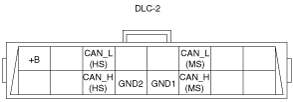
DLC-2 Outline
am3zzn00000281
|
|
Terminal name |
Function |
|---|---|
|
B+
|
Battery positive voltage
|
|
CAN_H (HS)
|
CAN communication line (HS)
|
|
CAN_L (HS)
|
CAN communication line (HS)
|
|
GND1
|
Ground (chassis)
|
|
GND2
|
Ground (signal)
|
|
CAN_H (MS)
|
CAN communication line (MS)
|
|
CAN_L (MS)
|
CAN communication line (MS)
|